We provide a diverse product selection, educational and quantity discounts, useful resources and specialized support. Can I use a MOSFET to connect the voltage divider just before reading the voltage? Ratio is multiplied with voltage at Rbottom for actual voltage value. For these boards the input range is 0 to 3.3V.

Looking forward to getting feedback on our design. The expected voltage range is 40-65v. But still their are some cleaver ways to do so. Your source impedance is 4.7 k. Help understanding several components in the sch of eMonTx 3.4, http://www.maximintegrated.com/en/app-notes/index.mvp/id/1957. JavaScript seems to be disabled in your browser.
We just received the PCB boards in the mail and and already found a minor issue with them: the pads for the DCDC supplies are flipped from where they should be (at the opposite edge of the part than where they belong). How to read high voltage (40-65v) from a Solar Battery bank, electronics.stackexchange.com/questions/42710/, Measurable and meaningful skill levels for developers, San Francisco? @SolarMill, thanks for sharing your progress. UL2003 input is connected to multiplexer output. I hope it makes sense to readers about the calculations. If all goes well, we'll proceed to work on the Hall effect portion of the design.
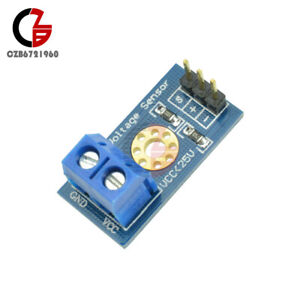
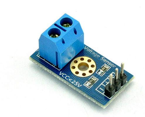
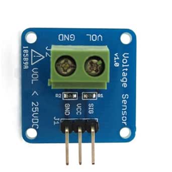
arduino voltage sensor robot standard okystar 
I've got a 2560 here that draws 62.5mA on the 5V rail when all inputs are configured as inputs (the power-up default) with nothing connected. rev2022.7.29.42699. When flying from Preclearance airports to the US, do airlines validate your visa before letting you talk to Preclearance agents? 2020 RobotShop inc. All Rights Reserved.Putting robotics at your service is a trademark of RobotShop inc. Hi @smurphy0620 welcome to the RobotShop Community.
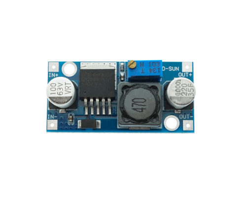
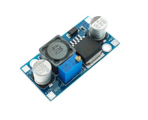
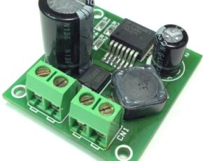
lab electronics 24v dc 48v 5a step electronic using converter arduino ublox oled neo gps module Wow thank you so much for a great explanation.
voltage This is because we used high value resistors in our divider to minimize the wasted power. We are using the standard EmonPi to monitor all incoming grid power though our main breaker box. During charging battery voltage can increase to 18 volts. Can adjustable constant current/voltage source be made with Arduino? Let's simplify by initially calculating the resistance required if R1 & R2 were combined into a single resistor: I would go further and say double that because I never like operating a resistor right on its maximum power rating. So it would seem that "the Arduino's impedance varies while sampling, in such a way that the voltage divider's output will be affected. A typical ADC clock rate is 125kHz, so a conversion takes 104 usecs, the first 12 usecs of which is charging the cap. For example, Free shipping on orders over USD $ 100.00 *, Data Communication and Human Input Devices, Defense, Security, Surveillance & Inspection, * Subject to approval and not available for products shipped by others sellers through the RobotShop Marketplace, My order was quickly processed and shipped. Are Banksy's 2018 Paris murals still visible in Paris and if so, where?

We can't feed this output directly to the Arduino though. Batteries are connected in series to increase the voltage output. It also has the longest history of robot competition since 1996. Was thinking something along the lines of a Raspberry Pi PICO and a bluetooth or WIFI module in each scale which is speaking to an RPI self hosting a wifi network / bluetooth host to receive the data and display it. It's just that alot of the designs used around here do monitor signals with a source impedance of roughly 10K and with no op-amp between them and the ADC input, so if there were a problem with a 4.7K source impedance, people would rightly want to know more. I made a simple diy project with the same above logic.
Values of R1 = 49.5k and R2 = 500 would also work. Using optocouplers is another way to do the same task. Using an esp8266, how can I create a circuit to measure 2 different analog inputs (not simultaneously) with only one ADC pin available (A0), How to select which resistor is required for my curcuit to reduce voltage.
However, if you are interested, a op-amp circuit can be built from a 741 IC (among others) and is configured like this: It sounds as if you have tried using far too small a value resistors. So while, dBC, your result falls within my definition of "several times", I restrained myself to "well in excess". Edit: The OP tells me that they get a max analog reading at 3.0V not 3.3V. Math Proofs - why are they important and how are they useful?
sensor Also do isolated DC Current measuring with the ACS 758. Now if 18 volts are at battery side it will be divided across resistors, 5 volts drops at 10k resistor and remaining 13 volts drops at 26k resistor. In parallel combination voltage across each battery remains same. Otherwise, they look great. This ratio is utilized in code for predicting the actual source/battery voltage.
max471 votage arduino I'm still not sure about the best way to do this, though. CT clamps will not work with DC.
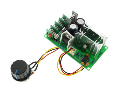
okystar 48v 36v governor In this post i am going to enlist some of the ways through which we can measure individual battery voltage which is a part of series or parallelconnected string/array of batteries.

We know Vout can be up to maximum 5 volts since nodemcu works and accepts maximum 5 volts at its I/O pins.
The formula to calculate the output voltage is: I would up R1 to 100kOmega; as it will only result in a 1% error. The design is somewhat restricted because it does not provide you with galvanic isolation on the voltage, and as a consequence of that it requires the battery negative to be both earthed and the common GND connection for the Arduino. Here are some options: https://www.robotshop.com/en/1-channel- Hey guys Im back! Arduino Stack Exchange is a question and answer site for developers of open-source hardware and software that is compatible with Arduino. 3) Draw an insignificant amount of current relative to the ratings of the solar panels. The question now is how the 3.33 volts is converted to 12 volt by nodemcu or how from 3.33 volts we can predict that at the battery side the voltage is 12 volts. So always use sufficient amount of resistors for bigger ampere hour batteries. Are those two benefits worth the inclusion of a $2.65 part? Digital pins of microcontrollers are required to activate the relay coils and for individual battery an individual pin is required. We are able to scalethe values we are working with: the 23v possible range of our battery state of chargehappens in the upper 35%of what would otherwise be a 0-65v measurement. Since we had to make a minimum of 6 of them, we have 4 more available for sale (fully assembled)if anyone is interested. Note: For the above circuit the resistors values should be selected using the same formula given above.
So battery-2 is supplying 13 volts in series string array. The pcb layout also restricts it to low battery voltages, and it will not be possible to use it - even leaving off the dc-dc converters - on higher voltages because of the minimal creepage distance between battery positive and GND (= battery negative). This is where the OPAMP might come into play. The technique is to measure the voltage across high potential battery first, than against the lower ones and negating the subsequent batteries voltage from the one at higherpotential. Two cases are given above when source is at 18 volt and when source is at 12 volt in both the cases the ratio comes out to be constant value.
30a In the above scenario for each battery their must be a dedicated analog channel. It's always like that! Solar charge controller also output voltage approximately equal to 15 volts to charge the batteries. Optocouplers also increases the circuit cost.

Considering thatthe opamponly cost $2.65, it seemed like a safe route to go with some additional perks along the way. They will draw a maximum of 65V/(360K + 5K6) = 0.18mA and the 360K resistor will dissipate about 10mW.
poe robotdyn 9v We'll write a follow up with a bill of materials and the design files. Closest equivalent to the Chinese jocular use of (occupational disease): job creates habits that manifest inappropriately outside work. Check out our engineering forums, Getting started with MicroPython on ESP8266, How to use MicroPython with ESP8266 and ESP32 to connect to a WiFi network, Using MicroPython SSD1306 driver to interface an OLED display with ESP8266 & ESP32, How to use ESP8266s sleep modes in MicroPython, MicroPython: Time-related functions, timers & interrupts in ESP8266 and ESP32, MicroPython Reading analog signals in ESP8266 and ESP32, ESP8266/ESP32-based WiFi access point using MicroPython, How to achieve longer MCU battery life with low power sleep mode, Infineons CoolSiC devices support Deltas bi-directional inverter, Qualcomm and Mahindra to provide immersive in-vehicle experiences, Diodes launches high-efficiency synchronous boost converter, Help designing 1.6KW Isolated AC/DC with Constant Current Output, Help with Zero Crossing Detector with the 16F877A code on MPLAB XC8. Maybe the board you have has different built in scaling. What happened after the first video conference between Jason and Sarris? I am going to measure voltage across Rbottom and i decided its value randomly to be 10k ohm. Since the resistor values are fixed we can calculate the voltage ratio across the resistors with respect to the source and use it in code for actual voltage at source. So higher is better but unfortunately you also need 2) that resistance to be low compared to the input impedance of the analog input. Eventually the voltage monitoring PCB and the Hall effect PCB can be combined into a single unit much like the EmonTX. Were selling off the extras for anyone thats interested.
The technique is to measure the voltage across high potential battery first, than against the lower ones and negating the subsequent batteries voltage from the one at higherpotential. Do we just connect the unused pins to ground or do we need a resistor in there? I used ULN2003 relay driver to drive the relay coils. For example for the above circuit the measured voltage across battery-1 is 48v and battery-2 is 36v. Click the below button to take the tutorial. I'm watching this too! Pros. See the circuit below. RoboCup is the largest scientific annual event to advance A.I., robotics and automation in the world. I would like to monitor the battery voltage of a 48v solar battery system. How can we send radar to Venus and reflect it back on earth? Negating 48v-36v=12v gives us battery-1 voltage. Here we need some important considerations to be taken seriously. Stack Exchange network consists of 181 Q&A communities including Stack Overflow, the largest, most trusted online community for developers to learn, share their knowledge, and build their careers. What does "Check the proof of theorem x" mean as a comment from a referee on a mathematical paper? More like San Francis-go (Ep. Theres been several posts about this topic and weve used that knowledge to help point us in the right direction.

These calculations will also be suitable for 1/2 Watt and 1 Watt resistors. However, we still need to measure the current of some additional DC loads that do not go through the inverter and we also need to measure the voltage levels of our battery bank. These three systems combine to prepare a highervoltage DC signal for input into an Arduino.
arduino bms 48v balancer bike topic 13s battery diy help project tomgeorge A few days after sending off the board design for printing I came across some comments in another thread about tying down the unused opampsto reduce noise and power consumption. With the new TurtleBot 4 Mobile Robot coming soon this fall, the next-generation robotic platform for learning the Robot Operating System (ROS), it's more relevant than ever to take a look back at how the TurtleBot came to life.

All with email notifications. That wasthe assumption we were operating on, based on comments in other forums about the need for an opampbetween a voltage divider and the analog input pin. So voltage divider is used here to divide the voltage in two half while ensuring that the one half voltage can not increase 5 volts in any scenario(charging etc). 300 or 330 (optional). Now lets calculate the values for Rtop and Rbottom.
Arduino relay is used in the project. The "TurtleBot" might have the name of one of nature's slowest creatures but make no mistake, this powerful piece of equipment represents a rapid leap forward for robotics development. All Rights Reserved. Thanks. What is the correct reading of in ""? We are also using a stock EmonTX to measure the AC output of our Outback VFX3648Inverter. However, if you are running a 24v or 12v setup, all you need to do is change the resistor values and swap out the DCDC power supplies to another model in the same series. So their pins are also working on 5 volt TTL logic.

Next Steps So far this article has been helpful, it talks about a voltage divider with a opamp to get more accuracy, but I need a bit more advice from someone that knows more than myself. Battery monitoring with 3.3v tolerant microcontroller.
acs712 20a