Using wire strippers, remove about 1 cm of insulating material from the ends of each of the two lengths of insulated copper wire. Make Your Own pH and Salinity Monitoring System, Atlas Scientific Conductivity Sensor K1.0 Kit, Atlas Scientific Basic EZO Inline Voltage Isolator, https://github.com/Atlas-Scientific/Ezo_I2c_lib/blob/master/Examples/Projects/pH_EC_led_indicator/pH_EC_led_indicator.ino, Temperature Compensating Atlas's Conductivity Sensor, Connecting Multiple Sensors to One Arduino Uno Serial Port, Water Quality Monitoring and Notification System, Or a STEMTera board (https://www.sparkfun.com/search/results?term=stemtera). Once students have finished testing the solutions, direct them to dispose of all solutions in a sink drain and clean up their lab work spaces. Afterwards, you will build on your understanding of how the conductivity probe works to design and conduct an experiment of your own. solution is added and the pH decreases. Engineers often design sensors to fit their exact needs. 3 -
Use appropriate symbols, numbers, and words to communicate key ideas about technological products and systems. In a hands-on activity, students build a conductivity tester to determine whether different objects are conductors or insulators. a zip folder from GitHub onto your computer. Do you agree with this alignment? Plan and conduct an investigation to gather evidence to compare the structure of substances at the bulk scale to infer the strength of electrical forces between particles. Atlas Scientific does not make consumer electronics.
Also, I'm not worried about rusting or long term effects from electrolysis because the water is not used for plants or drinking or anything like that. Then the two wires are taped onto opposite sides of the pen barrel. a project of D2L (www.achievementstandards.org). You can use either an Arduino UNO or a STEMTera board. Calibrate the sensors. In this case, the limits are as follows: If the conductivity reading goes over 500 S/cm, the yellow LED will turn on; if the pH reading goes over 10, the red LED will turn on. 12), laptop or desktop computer with USB cable and Internet access, 2 x 20 cm lengths of 22 gauge single-strand insulated copper wire; available at hardware stores, 2 x 10 cm lengths of 32 gauge nichrome wire; such as from, plastic barrel from a disposable pen, such as a BIC pen, four plastic cups, for the four test solutions, half-size or larger breadboard, such as the reasonably priced boards at, assorted jumper wires, such as a pack of 30 7-inch wires (PRT-11026) at, 470 resistor, such as the resistor multipacks at, red LED, such as the basic red 5 mm LED (COM-09590) at, 2 x 9V battery connector, such as the heavy-duty 9V snap connectors at, 16 x 2 LCD display, such as the basic 16-character by 2-line display with black text on green background (LCD-00255 ROHS) at, 10K trimpot (aka trimming potentiometer, a small variable resistor), such as the trimpot 10K with knob (COM-09806) at, 10K resistor, such as the resistor multipacks at, 220 resistor, such as the resistor multipacks at, soldering iron(s), such as the reasonably priced solder at, lead-free solder, a few tubes to share among one class, such as solder available at, wax pencil or tape and marker, to label the cups, distilled water, expect 1 gallon to be enough for an entire class, paper towels, for drying the rinsed probes, additional supplies may be needed to enable students to use their conductivity probes to conduct end-of-activity experiments of their own designs, for example, solutions of common household chemicals, lemon juice, sodium hydroxide, ammonia, at varying concentrations and temperatures, How to use a breadboard to construct simple circuits, Be able to identify the LED, resistor, jumper wire and related electrical components used in the activity, Aqueous solutions, including how to make a simple solution, Basic lab safety for conducting experiments in a chemistry laboratory. Pass out the handouts and direct students to individually answer the four "preparing" questions on page 2. The probe measures resistance and translates the resistance as an indicator of conductivity. Reply The supplies for Part 1 are shown in Figure 1. How to connect multiple Atlas sensors to a single Arduino serial port. The initial pH and EC of water are measured. Each sensor needs a unique I2C address. The higher the conductivity of a solution, the less resistance to the flow of electrical current. This is however not always correct. Refer to Figure 9 for the completed circuit and Figure 10 for the circuit schematic. The serial monitor will open. That sensor should work for a while. Measure the conductivity of a solution at various temperatures. Another common application involves the use of conductivity probes to monitor the ionic content of water used within cooling towers since too highly concentrated ionic solutions can prematurely corrode components and cause safety hazards. However, if the solution contains only water molecules or a solution of water and other covalent solutes, no charged particles exist to facilitate the flow of charge so the resistance across the probe will be very high. As students begin Part 3, each group uses a computer connected to an Arduino UNO to upload its codes to the Arduino. b) Set sensors' protocol to I2C. If the solution contains ions, charge will be able to flow easily through the probe (the resistance will be low). (Grades 9 - 12). Then students follow the handout instructions to repeat the testing of the four solutions they created in Part 2, this time recording in Data Table 2 of the handout the numerical relative conductivity values displayed on the LCD screen. Build and Test a Conductivity Probe with Arduino. Once students have finished answering the questions, review their responses as a class before starting the lab activity, as described in the Assessment section. Subject Areas:
Make sure the longer leg of the LED is connected to the positive voltage source. Thanks for your feedback! A HIGH pin will be the positive and a LOW pin will be the negative. There are 4 seperate parts to the sensor; the resistivity sensor, the thermometer, the button and the display. The first step in making the salinometer is the wiring. Have groups proceed to construct their conductivity probes. 9 -
The steps below include the process of making this addition to the IDE. Present the Introduction/Motivation content to the class.
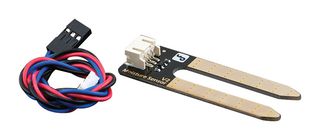
moisture soil sensor arduino dfrobot gravity analogue cpc compare analog Thanks for your feedback! Timing note: Plan on 40 minutes for Parts 1 and 2, building and testing the probe; 80 minutes for Part 3, connecting the probe to the Arduino; and 60 minutes for Part 4, critical thinking and analysis; for a total of 180 minutes. Finally we add the LCD display. Press question mark to learn the rest of the keyboard shortcuts. Advise students to take their time building the breadboard circuitry and frequently reference. From the reading you already have now, try to calculate the resistance between the electrodes. on Step 6. HS-ETS1-2. Since this sensor will be used in water, it is important to shield all electrical components from the water. Make sure students will have easy computer Internet access to the online reading and digital experiment for the critical thinking and analyzing portion of the activity (see links on the handout and in the Additional Multimedia Support section), especially the CK-12 links that require (free) account access.
Once the circuits are checked by the teacher, students test their probes by immersing them into cups of four different solutions: salt water, sugar water, distilled water and tap water. For this sensor we built three seperate housings; for the electrodes, for the Arduino and wiring and for the LCD display with the button. (Grades
We made it to look nice, but it can be done in any other way, as long as the circuit and code are the same. then perhaps you should fine tune the resistor and/or the distance between the electrodes to improve your sensibility. Looks like a fun project. Any other thermometer can be used, but in this guide only the wiring for the DS18B20 will be provided. A system to maintain the pH level of a sample within a defined range. Thanks for your feedback! Expendable Cost/Group: US $5.00
To avoid electrolysis we put an AC current over the electrodes. or not. Connect the hardware as shown in the schematic above. current: A quantity representing the rate of flow of electric charge, usually measured in amperes. Review their answers to gauge their depth of comprehension. Integrate a conductivity probe into a simple circuit. In accordance with the sample code for this project, the following addresses are used: pH sensor address is 99, and salinity sensor address is 100. Reply The LCD and button were put in a case made for the LCD display we conviently had lying around. Both are simple to make; students stir in a spoonful of either salt or sugar into a cup filled halfway with distilled water. For information on how to change between protocols and assign addresses, refer to this LINK. When using these materials with younger (grades 9-10) students who have limited coding experience, provide them with the Arduino file, Conductivity Sensor with LCD code, since entering the code can be a frustration point. Once groups have constructed their circuitry and had it verified by the teacher, they open the Arduino software on their computers and use a USB cord to connect the Arduino to the computer. Set the baud rate to 9600 and select "Carriage return". I think the sensor would last long enough before having to change its probes as I'm gonna have its voltage source enabled only when a reading is needed.
Some NaCl (salt) is added to the water, the conductivity reading rises and as soon as it crosses 500S/cm the yellow LED turns on. The LED must have its long leg connected to the positive battery end. The appropriate files are now included. For this we need the following: Since the aim is to measure seawater, we want to avoid electrolysis which makes the electrodes oxidize and that in turn will make the resistance increase rapidly over the first second of the measurement. This is the basis for the conductivity probe that students fabricate and use. In this lab activity, we will make a probe to use as a tool to determine very quickly whether a solution conducts electricity (ZAP!!) Refer to the following: Ezo pH datasheet, Ezo EC datasheet. When the reading is less than 10, the red LED turns off. See a few example discussion questions in the Assessment section.
How to make a benchtop pH meter with an Arduino Uno and the Gravity analog pH sensor from Atlas Scientific. However, these contents do not necessarily represent the policies of the NSF, and you should not assume endorsement by the federal government. solution is poured into the beaker, the pH increases and upon crossing 10 and the red LED turns on. In the ASN, standards are hierarchically structured: first by source; e.g., by state; within source by type; e.g., science or mathematics;
PS: We do not share personal information or emails with anyone. Point out that this value is related directly to how easily electrical current can pass through the solution.
salinity arduino Did you make this project? Once groups have completed recording their results in Data Table 1 of the handout for Part 2, make sure they save their solutions for use later in Part 3. The Arduino and wiring were put in a protective box for plugs. It is a relatively low cost and easy sensor to build. Compile and upload the pH_EC_led_indicator code to your, on your keyboard. c) Copy the code from pH_EC_led_indicator onto your IDE work panel. Check for Understanding: As students progress through Parts 1, 2 and 3, expect them to be able to describe how they know that a solution is conductive. Measure the conductivity of solutions of varying concentrations. Outside of the chemistry classroom, students may have heard of "electrolytes" and "nonelectrolytes," words that are synonyms for ionic compounds and covalent compounds, respectively. Have students follow the handout instructions to gather supplies and proceed. Then solder the wires together to make a strong connection, as seen in Figure 4. One part switches around the polarity and the other takes a measurement when the 8-pin is HIGH and the 7-pin is LOW. 3 months ago. probe: A small device, especially an electrode, used for measuring, testing or obtaining information. Well you could go for any conductive material, but steel will start rusting of course. You can also access it from the Ezo_I2c_lib zip folder downloaded above. It also includes a simple embedded model of a conductivity sensor setup and five questions for students on the topic of electrolyte solutions and conductivity. . http://www.fivecreeks.org/monitor/sal.shtml. In designing a desalination plant, engineers must be able to measure the amount of salt present in seawater and in the fresh water produced; a conductivity probe is a valuable instrument to identify the presence or absence of ionic compounds. Preparing: Before beginning the lab activity, direct students to individually answer the four questions in the "preparing" section of the Build and Test a Conductivity Probe Lab Handout, on page 2. The less oxidation, the better. From one side the power cable could be let in and from the other side the electrodes and thermometer cables could be let out. Identify whether a solution is conductive. Once we have built the probes, we will look at two different ways to display the resultsusing light as well as an LCD numerical display. The goal of the sensor is to have a reading that changes as the concentration of salt increases or decreases in the water over time. Operation is via I2C protocol and readings are displayed on the Arduino serial monitor. The serial monitor will open. That's because the circuit is a actually voltage divider right?

conductivity: The degree to which a specified material conducts electricity, calculated as the ratio of the current density in the material to the electric field that causes the flow of current. The code for the sensor alone to work is below. The activity also uses non-expendable items such as Arduino UNO microcontrollers, breadboards, LCD displays and computers; see the Materials List for details. Look for common circuitry mistakes related to the LED. In the IDE, go to Sketch -> Include Library -> Add.ZIP Library -> Select the Ezo_I2c_lib folder you just downloaded. Proofread (and modify as necessary) all proposed procedures before permitting groups to proceed to conduct their designed lab experiments. Each sensor needs a unique I2C address. I'm going to try it out. Refer to the following Emerson Process Management application data sheet, Theory and Application of Conductivity, for an overview of typical ways conductivity is utilized in industrial processes. The LEDs are turned on if the sensor readings go out of the predefined limits. Rember it must be close to the resistance of the resistor you have in the circuit. The process was fairly easy, but is necessary to have a working sensor which can also say something about the salinity. Custom NanoLeaf Lights! You might find something else like this, but for us this was perfect. You know your correction factor is correct when the "Corrected resistance" does not change while the water cools down. Do NOT correct student predictions at this point.). During the activity, students require access to the following Internet resources: In addition, the CK-12 Foundation has an excellent little web app that serves as an appropriate follow up for students after completing the activity. Encourage students to make additions/modifications to their handout answers as a result of the discussion. Note that we use a "known" resistance which is being used to measure the "unknown" resistance of the water. https://thecavepearlproject.org/2017/08/12/measuring-electrical-conductivity-with-an-arduino-part1-overview/. Then they answer three handout questions. www.teachengineering.org/activities/view/nyu_probe_activity1, Search curriculum by Common Core standards, Click to view other curriculum aligned to this Performance Expectation, Build and Test a Conductivity Probe Lab Handout, Build and Test a Conductivity Probe Lab Handout (docx), Build and Test a Conductivity Probe Lab Handout (pdf), Arduino Code Comments for the Teacher (docx), Arduino Code Comments for the Teacher (pdf), Build and Test a Conductivity Probe Lab Handout Answer Key (docx), Build and Test a Conductivity Probe Lab Handout Answer Key (pdf), Larger Figure 11: Breadboard Circuitry (png), Statistical Analysis of Flexible Circuits, Exploring Nondestructive Evaluation Methods, https://learn.sparkfun.com/tutorials/how-to-solder---through-hole-soldering?_ga=1.165393596.20730219.1441226013, https://www.emerson.com/documents/automation/application-data-sheet-theory-application-of-conductivity-rosemount-en-68442.pdf, http://www.ck12.org/chemistry/Electrolytes-and-Nonelecrolytes/lesson/Electrolytes-and-Nonelectrolytes-CHEM/, http://www.ck12.org/assessment/tools/geometry-tool/plix.html?eId=SCI.CHE.432.4&questionId=53ceca67da2cfe48ba6cfc9a&artifactID=1817915&backUrl=http%3A//www.ck12.org/chemistry/Electrolytes-and-Nonelecrolytes/%23interactive. Question If yes then I just picked up on that :P, Press J to jump to the feed. The measurement of conductivity is typically a measure of how easily electrical current is able to move through a solution. Example discussion questions: When soldering the wires in Part 1, require students to wear safety glasses and be sure they know that a soldering iron is extremely hot, even for several minutes after it is unplugged. a) Calibrate the sensors. 3 -
Have groups proceed to follow the handout instructions to each make two solutionssalt water and sugar water. This activity was developed by the Science and Mechatronics Aided Research for Teachers with an Entrepreneurial ExpeRience (SMARTER): A Research Experience for Teachers (RET) Program in the School of Engineering funded by National Science Foundation RET grant no. How to temperature compensate the Atlas conductivity sensor automatically. This device was developed and tested using a Windows computer. The pH and salinity sensors from Atlas Scientific are used. It is important that the trimpot used in this circuit is used solely to adjust the contrast on the LCD screen. This equipment is intended for electrical engineers. Our sensor was already calibrated, so will not discuss calibrating the thermometer in this guide. Utilize an Arduino with LCD display-to-display probe values. Let's start with the resistivity sensor. On your computer, open the Arduino IDE (You can download the IDE from, if you do not have it). Encourage students to feel free to design experiments that use the Part 2 or Part 3 lab activity setup. Ability to use sensor readings to control other hardware.
within type by subtype, then by grade, etc. Examples of what students might test: Monitor conductivity while an acid is added to a base, such as lemon juice added to a dilute solution of sodium hydroxide or ammonia. Breadboard / welding camps / perfboard and soldering equipment, 4.7k Ohm resistor(or any other if specified by other manufacturer). onto your IDE work panel. Engineers planning solar panel installations require sensors that measure the amount of light falling on a given area. Hence, if the solution has a high resistance, such as with a nonelectrolytic solute, the conductivity will be very low and if the solution has a low resistance, such as with an electrolytic solute like table salt, the conductivity will be very high. 3 months ago This requires groups to design additional experiments that utilize their conductivity sensors. solvent: The liquid in which a solute is dissolved to form a solution. This ensures that the text and numerical values are visible on the LCD display when the code runs for the first time after students upload it. It also measures temperature to compensate for temperature changed resistance. Most of the articles would mention using a the Atlas EC Kit which costs about 200$. (Grades
The conductivity probe uses simple electrical circuits to communicate the measurement to the user. Now to we add a button to start a measurement. Review what is necessary in order to form a solution, that is, a solute dissolved into a solvent. Each sensor has a unique calibration process. Set the baud rate to 9600 and select "Carriage return". Different patterns may be observed at each of the scales at which a system is studied and can provide evidence for causality in explanations of phenomena. In this project, we will be making a pH and salinity/conductivity monitoring system with LED indicators. I'm trying to make a sensor to measure the salinity in a water tank. This is only for visuals). (optional/alternative approach: Have students share their responses prior to sorting into groups to start the experiment. solute: The minor component in a solution, dissolved in the solvent. In this guide only the wiring for that display will be shown(Please note that in the schematic another LCD display was used. HS-PS1-3. a) Download Ezo_I2c_lib, a zip folder from GitHub onto your computer. Get the inside scoop on all things TeachEngineering such as new site features, curriculum updates, video releases, and more by signing up for our newsletter! We already showed a bit of code after the wiring of the resistance sensor to find out if everything was working. The movement of these positive and negative ions enables the flow of charge through the solution. The 220 resistors limit the current to the LEDs, preventing them from blowing out. The thing is that the water could start with having small amounts of salt and with time the concentration would increase. Measure the conductivity of various common household chemicals. This lab activity requires students to make simple solutions by dissolving various solutes into measured volumes of water. Refer to Figures 2 and 3. If you are always getting the same reading, then perhaps you should fine tune the resistor and/or the distance between the electrodes to improve your sensibility. The appropriate files are now included. This was a project for the minor Delta Expert at the Delft University of Technology. Operation is via I2C protocol and readings are displayed on the Arduino serial monitor. Fundamentally, the probe measures the resistance to the flow of charge and must be submerged within the testing solution to work. Students gain an understanding of the difference between electrical conductors and insulators, and experience recognizing a conductor by its material properties. ), What other uses might your Part 3 sensor setup serve? A solution conducts electrical current when charged particles (ions) are in the aqueous solution. Copyright 2015 Phillip Cook, Polytechnic Institute of NYU, Copyright 2015 Phillip Cook, Polytechnic Institute of NYU; image made with fritzing.org. As said in previous step, it is very important to have the electrodes at a fixed distance from eachother. The very first important step in this process is to have the electrodes at a fixed distance from eachother. You can also access it from the Ezo_I2c_lib zip folder downloaded above. They enter the code provided on the handout (or copy/paste the code if a digital version of the handout is made available). Divide the class into groups of three or four students each. Now we will add the full code to work with the entire sensor. The STEMTera board was used in this project for its compact design where the Arduino is combined with the breadboard. I can tell you from years of working on oceanographic research ships that if you have the conductivity of the water and the temperature, you can calculate salinity. DIY, Wireless, Modular, Arduino, 3D Printed! Next, twist one of the nichrome wires onto the exposed copper end of one of the insulated wires. Answer We use a relatively simple code to measure the resistivity. You will have to add them to your Arduino IDE in order to use the code. Determine the conductivity of an unknown solution. 8), Define a simple design problem reflecting a need or a want that includes specified criteria for success and constraints on materials, time, or cost. Since an Arduino is DC we have to use a trick to make something that is close to AC; we use two digital pins between which we rapidly switch around the polarity. The. nonelectrolyte: A substance that does not readily ionize when dissolved or melted and is a poor conductor of electricity. *The NGSS logo is a registered trademark of WestEd. The primary function of the probe is to indicate the ease with which electrical current can flow through a solution; the easier current flows, the higher the conductivity. It's in ohm, but you can change the code with some calculations so if gives anything else. 6 -
We need the following components: For this example the DS18B20 waterproof digital thermometer was used. The easiest way to do this is by taking hot water and measuring the resistance while it cools down. Free K-12 standards-aligned STEM curriculum for educators everywhere. Does it have to be copper or can it be any conductive material? Why did tap water have a measureable conductivity in Part 3, but not light the LED in Part 2? Can you please tell me the units the salinity is displayed in? Plan and conduct an investigation individually and collaboratively to produce data to serve as the basis for evidence, and in the design: decide on types, how much, and accuracy of data needed to produce reliable measurements and consider limitations on the precision of the data (e.g., number of trials, cost, risk, time), and refine the design accordingly. When groups show you their circuit boards to check the connections, make sure that the trimpot is in the middle of its range of motion. If engineers are dealing with aqueous or liquid solutions, it is quite common to characterize a solution's conductivity to gain insight into the types of solutes dissolved within the solution (either ionic or covalent solutes). There is a classic piece of equipment called a CTD - which stands for Conductivity Temperature and Depth. b) On your computer, open the Arduino IDE (You can download the IDE from HERE if you do not have it).

Then review and discuss students' responses to the questions to make sure they understand the role of the probe, its real-world applications and the types of substances that the probe helps to identify as being present or absent within solutions being analyzed. In the second experiment, the feedback comes in the form of a digital numerical readout (constituting a quantitative measurement) in which, as the numerical value displayed increases, the conductivity of the solution increases. They are challenged to determine if the fabrication process results in a change in the circuit dimensions since, as circuits get smaller and smaller (nano-circuits), this c Students learn about nondestructive testing, the use of the finite element method (systems of equations) and real-world impacts, and then conduct mini-activities to apply Maxwells equations, generate currents, create magnetic fields and solve a system of equations. 1132482. During this final component of the lab activity, students work together to complete the "critical thinking" portion of the lab activity as presented on the handout. Conclude by facilitating a class discussion to share, compare and distill experiences, results and conclusions. Do you agree with this alignment? From this data a correction factor can be computed. It consists of two parts. Through this lab, students are exposed to multiple ways that a conductivity probe can be used and challenged to consider its possible real-world applications. A hot glue gun was used to make everything waterproof.