5.
fgr Disconnect power to unit at main panel.
Installing a Switch for a 240 Volt Specifications Wire Lead: Outlet Dia: N.W. It will. Push the switch down until the bottom of the switch sits firmly on the bottom of the condensate pan. with the wiring diagrams There is a common point and only three other terminals on each side of the switch 4 position rotary switch wiring diagram premium 5 way rotary switch wiring diagram prs tearing The motor operates with 4 wires At 110 v your black wire (hot) should be broken by a switch, and the white wire (neutral)
Rule-A-Matic Float Switch - RULE INDUSTRIES - PDF Catalogs The Low Sensitivity Electronic SAFE-PAK eliminate the need for explosion proof enclosures.
Aug 4, 2008 #2 Re: Mayfair Bilge Pump with Float wiring diagram Mayfair Bilge Pump with Float wiring diagram You guys make boating a great hobby. The magnet float starts the pump (4) when bilge water reaches 50 mm. 1. The Johnson Electro Magnetic Switch is reportedly more reliable than the typical flipper switches. 3: Unit Mounting Detail RELAY INSTALLATION INSTRUCTIONS CAUTION: To prevent ignition of ammable or combustible atmospheress, disconnect power before servicing
Best Sump Pump Float Switch Reviews 2021 DOL Starter (Direct Online Starter) is also knows as across the line starter. A Universal Electric Motor is designed to operate on either alternating current or direct current (AC/DC). Incorporating both switch wires in the red circuit will shut the unit completely off. It will. Water Level Controls float switches work by using probes instead of float switches. The only problem is that the wiring diagram provided is useless. If you are looking for a float switch that is compatible with most sump pumps, then THE BASEMENT WATCHDOG Model BWC1 is the best bet. Float Switches Design and Function BERNSTEIN float switches are designed as contactless magnetic switches. 8 Pics about 3 Phase Magnetic Motor Starter and Wire Diagram - YouTube : Wiring Diagram For Motor Starter 3 Phase Controller Failure Relay, Help Please ~ Wiring the Switch to the motor and also float switch wiring diagram for water pump - YouTube | Solar powered.

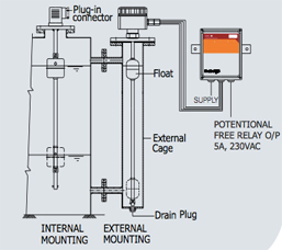
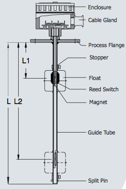
When controlling a 240 volt motor, it is best to install a double pole switch for this irrigation pump. When the effects of shock, wear and vibration are minimized, these hermetically sealed reed switches provide precise repeatability and consistent actuation points over the life of the float switch. Ordering information: direct mounting vertical float-type level switch The Standard offering represents the most common options.
Instruction manuals Switches will
Magnetic How to Wire a Contactor wiring diagram for contactor and overload float level switch guided magnetic tds specification Float Switches Intrinsic Relay Wiring Diagram 3 phase contactor with overload wiring diagram pdf
Magnetic Switch Wiring Diagram WIRING DIAGRAMS O d u c 1 O n i n manual and magnetic across-the-line starters may be applied.
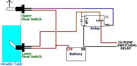
Basic Wiring for Motor Contol - Eaton pump water tank float well automatic switch controller simple circuit control relay switches borehole problems reuk automation diy header How to wire a bilge pump | ON-OFF bilge switch - New Wire Marine contactor C. When the bilge water has sunk to level 3/4", air is let in through the air opening (6) in the float house. The Open or Close of the Contacts indicates the High or Low Alarm.
Data Sheet: Mobrey Vertical Magnetic Level Switches Magnetic Contactor is for lossy magnetic flow generated with current in winding of such devices as transformer, throttles, magnetic cartridges filters and circuit. 3-Wire Thermostat Type BA Float Switches Switch Left Symbol Front Single Deck Bulletin 815 Right Auxiliary Contacts (When Used) We have step-by-step solutions for your textbooks written by Bartleby experts! It is mostly used to regulate 240V appliances. The purpose of this document is to provide a simple cross reference of common schematic/wiring diagram symbols used throughout various parts of the world.
Mechanical flow switches - Magnetrol on vidio float switch wiring diagram for water pump Float Switch Connection Single Phase Water Pump what is float switch?
Bilge pump switch wiring trick | Shamrock Boat Owners' Club KOBOLD level switches can be mounted in the tank top or bottom, or can be adapted for side mounting. l The schematic or line diagram includes all the components of the control circuit and indicates their function. Either of the Two Start Buttons will close the contactor, Either of the STOP buttons will open the Contactor.
How Do Float Switches Work (Diagram & Working Principle) Float switch wiring help Float Switches | McMaster-Carr The float sensor consists of an electromagnetic switch. No metal parts in contact with liquids. Order History; Punchout. 4. Low Sensitivity Electronic SAFE-PAK Relay. Figure 1 is a typical wiring diagram for a three-phase mag-
level magnetic float guided switch glass india AquaGuard AG-1200+ Horizontal Secondary Drain Pan 24v Mayfair Bilge Pump with Float wiring diagram - Boating Forum It is used for low rating usually below 5HP motors. 1 Less than a minute. Diagram switch wiring float tank automotive control. power source are disconnected or not powered while wiring the level switch. The movement of the float, due to changing fluid level, will cause the reed change to work (for instance close or open) at a specific level. When the liquid level rises in your typical storage tank, the float pivots upwards.
Direct Online Starter Measurement Principle.
Wiring In stock (10 items available) Stainless steel vertically mount liquid level sensor, 200 mm in length. File Type: JPG.
3 Float Switch Wiring Diagram - donner.medair.org flow switch wiring University of Minnesota am wiring a 220v contactor into a 220v  Magnetic Float Switches - Magnetic Float Level - Proximity
 Output of contactor is connected with the motor.
motor connection with magnetic contactor wiring diagram Tank Overflow Controller Using Float Switch Circuit - YouTube www.youtube.com. The stainless steel float and switch should be aligned at the height where low liquid level is a concern. F50: Disc actuated flow switch basic operating principle.
