 AIR CONTROL IN FLOWING WELLS Flowing wells or wells with little or no drawdown, could create a special problem in air control in the operation of your standard tank system. If necessary, reconnect the motor for 115 volts, as shown. serves as 9. 2872 0697 Standard TankFigure 16: Watch for Pressure Gauge Rotate AVCto Flutter 180 CCW 40 60 Disconnect 20 80 AVC Tube 100 40 60 20 80 100 Remove Gauge 2873 0697 Figure 18 Remove Disconnect Drain Plug PressureFigure 17: Close Regulator Valve Until Switch TubePressure Stabilizes 1065 0697 AVC Tubing Up to 100 ft run: Same size as pump discharge port. Pump delivers water but Pressure switch is out of adjustment or DISCONNECT POWER; adjust or replace pressure switch. 1. To change to 115 volts:1. base plate foundation anchor bolt screw levelling pump leveling plates installation pumps centrifugal baseplate steel washer sleeved grout chock between Improper priming 1. Check AVC for defects. Connect the ground wire to a grounded lead in a service panel, to a metal underground water pipe, to a metal well casing at least ten feet (3M) long, or to a ground electrode provided by the power company or the hydro authority. 4. Thread adapter flange onto Venturi suction pipe from well and align nipple and drive pipe. 1. Using PTFE pipe thread sealant tape tape on male threads, install special B-OVER THE WELL INSTALLATION STEEL PIPE SHOWN plastic pipe adapter (supplied with ejector) by screwing adapter into 474 0194 1-1/4 tapped hole in ejector body (see Figure 1). STA-RITE INDUSTRIES 293 Wright Street Delavan, WI U.S.A. 53115 Phone:1-888-782-7483 Fax: 1-800-426-9446 Web Site: sta-rite.com Capacitor voltage may be hazardous. Operation 9 40 60 PRIMING THE PUMP 20 80 NEVER run pump dry. Attach the ground wire to one of the grounding 4. a. Your motor terminal board (locatedunder the motor end cover) should look like one of those below. SSJC SSJD SSJE No. 4. Make sure power is off. Replace check valve or foot valve. Pump may draw well down far enough at this point to lose its prime.Figure 14: Adjust Regulator If so, close regulator valve until pressure is stable throughout pumping(See Figures 12, 13, 14) cycle. 7. Apply gasket to adapter Ejector flange, making sure that holes line up. Clean cavity from which seal was removed and clean motor shaft. To do so will void warranty.The label NOTICE indicates special instructions whichare important but not related to hazards. Slide threadless coupling down over drive pipe from well. In offset installations, pump suction port should be highest point in suction pipe; there should be no sags in suction pipe (run it straight and at a slight angle upward from well head to pump).ON OFF 1060 0697Figure 13: Start Pump
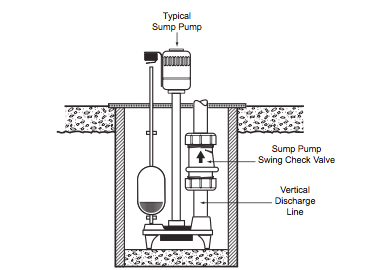
Leave room to use wrenches.Foot Valve & Strainer Foot Valve & Strainer Plug 1 drive port when installing on shallow well. Remove pressure gauge. WINTERIZING (Figure 18) 1. (Use gasket 5 Feet 8. b. Inspect ejector to make sure that nozzle and venturi openings are clean and clear.r) 2. Unions installed near pump and well will aid in servicing. 3. This type of well must be vented to the outside of any enclosure. Inspect shaft to make sure it is clean. 2. motor nameplate. b. IF NO PRESSURE OR NO WATER, REPEAT STEPS IN No.1 (above) two or three times to remove entrapped air from the suction pipes. Cut tubing to length to reach AVC; assemble 100 to fitting on pump and to AVC on tank. 5. Reinstall the Motor end cover. Installation 5 7. Incorrect voltage can cause a fire or seriously damage the motor and voids the warranty. Follow steps 1a, b, c under Winterizing, above. Check system by alternately opening and closing faucets in the system. Load Branch Fuse* (0 - 30) (31 - 61) (62 - 91) (92 - 122) Motor HP Volts Amp Rating Amp AWG WIRE SIZE (mm2) 1/2 115/230 12.4/6.2 15/15 12/14 (3/2) 10/14 (5.5/2) 8/14 (8.4/2) 6/12 (14/3) 6/12 (14/3) 3/4 115/230 14.8/7.4 20/15 12/14 (3/2) 8/14 (8.4/2) 6/14 (14/2) 6/12 (14/3) 4/10 (21/5.5) 1 115/230 19.2/9.6 25/15 10/14 (5.5/2) 8/14 (8.4/2) 6/12 (14/3) 4/10 (21/5.5) 4/10 (21/5.5)* Time delay fuse or circuit breakers are recommended in any motor circuit. Motor will not run Fuse is blown or circuit breaker tripped Replace fuse or reset circuit breaker. Water level is too low for shallow well A deep well jet package may be needed (over 25 ft. to water) setup to deliver water to deliver water. Pipes leak DISCONNECT POWER and open faucets until all pressure is relieved. Pentair Flotec FP4432-01 1 HP Vertical Deep Well Jet Pump, 260' for 4" or larger well / 180' for 2" well, Undersink & Countertop Filtration Systems, Residential Softening & Filtration Valves, Recreational Vehicle Plumbing Accessories, Turf Management & Pest Control Accessories, Water Treatment Solutions for Drinking Water, Water Treatment Solutions for Office Water & Coffee, Water Treatment Solutions for Warewashing, Residential Filtration Solutions Customer Service, Commercial Filtration Solutions Customer Service, Adjusting Well Pump Pressure Switches Instructions, Pentair Medical Carrier Transparency Reports, Do Not Sell My Personal Information - CA Residents Only, Superior performance at depths to water of 50' or more, Rugged, heavy-duty cast iron pump housing, Ready-to-install 230 volt motor - see manual for 115 volt conversion. Water pressure in the casing will then soak the cup seals. Consult Table II for proper venturi and nozzle. A precharged tank contains a factory Relief Valve provided air charge. 2. Check joints for leaks with soapy water. Inspect pipe for any foreign matter or obstructions. Capacitor voltage may be hazardous. p ump; then check Pump has lost prime through: In installation already in use: p rime before look- i ng for other causes. Connect ejector to first length of pipe. Wires at motor are loose, Refer to instructions on wiring (Pages 7 and 8). (Ask your well driller for this information. To change to 115 volts: Voltage is factory set to 230 volts. Pump does not Water level in well is lower than A new jet and venturi combination may be needed. 5. Remove paper backing from adhesive gasket. Move the voltage change plug to the 115 volt the dial window as shown in Figure 10. position. Tighten all hose clamps securely on plastic pipe. Motor runs hot and Motor is wired incorrectly Refer to instructions on wiring. shock hazard, use 3. IMPORTANT: Your pump pressure switch is set for a 20-40 PSI range andFigure 5: Pump With Pre-charged Tank2358b 0697 requires a tank pre-charge of 28 PSI for proper operation (see Figure 6). See installation instructions provided with tank and AVC. Well Seal 300 ft. to 600 ft run: Increase two pipe sizes.Figure 4: Pump With Standard Tank2355b 0697 PRESSURE TANK INSTALLATION DEEP WELL The Pressure Tank provides a reservoir of water under pressure and maintains cushion of air pressure to prevent pipe hammering and possible damage to plumbing components. Once unit has primed and pressure stabilized, slowly open (turn 20 80 counterclockwise - Figure 15) regulator valve until pressure falters (pressure gauge needle flutters; pump may become noisy - see Figure 100 16). Starting switch is defective DISCONNECT POWER; Replace starting switch. (AVC) AVC 2. Align locating lugs on pump base with lugs on adapter flange; attach Leathers pump to flange with cap screws provided. If there are other wires, they should be capped.7. b. Leaking foot valve or check valve 3. 8, 16, 17, 18, 19) J201-35 J201-35 J201-35 1 THE FOREGOING WARRANTIES SHALL NOT EXTEND BEYOND THE DURATION EXPRESSLY PROVIDED HEREIN.Some states do not allow the exclusion or limitation of incidental or consequential damages or limitations on the duration of animplied warranty, so the above limitations or exclusions may not apply to You. Ejector or impeller is plugged Clean foot valve or strainer. Electric al Code, and localGround pump before codes for all wiring.connecting to powersupply. base volute. Page General Safety2 Warranty..3 Installation4-6 Electrical7,8 Operation..9,10 Maintenance..10-12 Repair Parts ..13,14 Troubleshooting.. 15Limited WarrantySTA-RITE warrants to the original consumer purchaser (Purchaser or You) of the products listed below, that they will be freefrom defects in material and workmanship for the Warranty Period shown below.Product Warranty PeriodWater Systems Products jet pumps, small centrifugal pumps, whichever occurs first:submersible pumps and related accessories 12 months from date of original installation, or 18 months from date of manufacturePro-Source Composite Tanks 5 years from date of original installationPro-Source Steel Pressure Tanks 5 years from date of original installationPro-Source Epoxy-Lined Tanks 3 years from date of original installationSump/Sewage/Effluent Products 12 months from date of original installation, or 18 months from date of manufactureOur warranty will not apply to any product that, in our sole judgement, has been subject to negligence, misapplication,improper installation, or improper maintenance. Use two clamps perbetween adapter or moreand pump flange) joint to prevent air leaks into suction pipe. If there are other wires, they should be capped. See Discharge Pipe Sizes for information regarding correct dischargeFigure 3 pipe size. limed, causing excess friction Piping is too small in size Use larger piping. If less than pressure switch cut-in setting (20-40 PSI), pump air into tank from outside source until air pressure is 2 PSI Air charge too low in pre-charged tank less than cut-in setting of switch. c. Pump trying to lift water more than rated lift for deep well ejector used (including compensation for horizontal offset). Use PTFE pipe thread sealant tape tape on male threads. Maintenance 12Be Careful That Does Not Damage HOW TO HANDLE A GASEOUS WELLMotor Shaft Shoulder Seal Face In some areas well water contains gases which must be allowed to escapeCeramic Carbon before the water is used. Running pump without water may 100 cause pump to overheat, damaging seal and possibly causing burns to persons handling pump. Check locally for frost protection requirements (usually pipe must be 12 below frost line and pump must1-1/4\" Plastic Suction PipeSpecial 1-1/4\" Plastic Pipe be insulated). Remove pressure gauge to vent pump; drain pressure tank and all piping to a point below frost line. Make sure foot valve operates freely: attach to ejector with a close nipple. Repair Parts 13 1 89 10 2 115 3 12 4 13 14 6 7 2365 0396 REPAIR PARTS LIST Ref. Lift pump motor and adapter assembly off as shown. If possible, connect the pump to a separate branch circuit with no other appliances on it. See catalog for specifications. Check air valve for leaks (use soapy solution) and replace core if necessary. Make sure power is off.2. INSTALLATION OF NEW SEAL 1. 2. Heat pit or pump house. Never wire a 115 volt motor to a 230 volt line.Plug Type Voltage Selector Dial Type Voltage Selector Power Supply Connections Voltage Change Dial Pressure Switch Ground Wire ConnectionFigure 7: Voltage set to 230 volts, Plug Type Figure 9: Voltage set to 230 volts, Dial TypeVoltage is factory set to 230 volts. deliver water to full estimated capacity Steel piping (if used) is corroded or Replace with plastic pipe where possible, otherwise with new steel pipe. AIR CONTROL IN FLOWING WELLS Flowing wells or wells with little or no drawdown, could create a special problem in air control in the operation of your standard tank system. If necessary, reconnect the motor for 115 volts, as shown. serves as 9. 2872 0697 Standard TankFigure 16: Watch for Pressure Gauge Rotate AVCto Flutter 180 CCW 40 60 Disconnect 20 80 AVC Tube 100 40 60 20 80 100 Remove Gauge 2873 0697 Figure 18 Remove Disconnect Drain Plug PressureFigure 17: Close Regulator Valve Until Switch TubePressure Stabilizes 1065 0697 AVC Tubing Up to 100 ft run: Same size as pump discharge port. Pump delivers water but Pressure switch is out of adjustment or DISCONNECT POWER; adjust or replace pressure switch. 1. To change to 115 volts:1. base plate foundation anchor bolt screw levelling pump leveling plates installation pumps centrifugal baseplate steel washer sleeved grout chock between Improper priming 1. Check AVC for defects. Connect the ground wire to a grounded lead in a service panel, to a metal underground water pipe, to a metal well casing at least ten feet (3M) long, or to a ground electrode provided by the power company or the hydro authority. 4. Thread adapter flange onto Venturi suction pipe from well and align nipple and drive pipe. 1. Using PTFE pipe thread sealant tape tape on male threads, install special B-OVER THE WELL INSTALLATION STEEL PIPE SHOWN plastic pipe adapter (supplied with ejector) by screwing adapter into 474 0194 1-1/4 tapped hole in ejector body (see Figure 1). STA-RITE INDUSTRIES 293 Wright Street Delavan, WI U.S.A. 53115 Phone:1-888-782-7483 Fax: 1-800-426-9446 Web Site: sta-rite.com Capacitor voltage may be hazardous. Operation 9 40 60 PRIMING THE PUMP 20 80 NEVER run pump dry. Attach the ground wire to one of the grounding 4. a. Your motor terminal board (locatedunder the motor end cover) should look like one of those below. SSJC SSJD SSJE No. 4. Make sure power is off. Replace check valve or foot valve. Pump may draw well down far enough at this point to lose its prime.Figure 14: Adjust Regulator If so, close regulator valve until pressure is stable throughout pumping(See Figures 12, 13, 14) cycle. 7. Apply gasket to adapter Ejector flange, making sure that holes line up. Clean cavity from which seal was removed and clean motor shaft. To do so will void warranty.The label NOTICE indicates special instructions whichare important but not related to hazards. Slide threadless coupling down over drive pipe from well. In offset installations, pump suction port should be highest point in suction pipe; there should be no sags in suction pipe (run it straight and at a slight angle upward from well head to pump).ON OFF 1060 0697Figure 13: Start Pump
AIR CONTROL IN FLOWING WELLS Flowing wells or wells with little or no drawdown, could create a special problem in air control in the operation of your standard tank system. If necessary, reconnect the motor for 115 volts, as shown. serves as 9. 2872 0697 Standard TankFigure 16: Watch for Pressure Gauge Rotate AVCto Flutter 180 CCW 40 60 Disconnect 20 80 AVC Tube 100 40 60 20 80 100 Remove Gauge 2873 0697 Figure 18 Remove Disconnect Drain Plug PressureFigure 17: Close Regulator Valve Until Switch TubePressure Stabilizes 1065 0697 AVC Tubing Up to 100 ft run: Same size as pump discharge port. Pump delivers water but Pressure switch is out of adjustment or DISCONNECT POWER; adjust or replace pressure switch. 1. To change to 115 volts:1. base plate foundation anchor bolt screw levelling pump leveling plates installation pumps centrifugal baseplate steel washer sleeved grout chock between Improper priming 1. Check AVC for defects. Connect the ground wire to a grounded lead in a service panel, to a metal underground water pipe, to a metal well casing at least ten feet (3M) long, or to a ground electrode provided by the power company or the hydro authority. 4. Thread adapter flange onto Venturi suction pipe from well and align nipple and drive pipe. 1. Using PTFE pipe thread sealant tape tape on male threads, install special B-OVER THE WELL INSTALLATION STEEL PIPE SHOWN plastic pipe adapter (supplied with ejector) by screwing adapter into 474 0194 1-1/4 tapped hole in ejector body (see Figure 1). STA-RITE INDUSTRIES 293 Wright Street Delavan, WI U.S.A. 53115 Phone:1-888-782-7483 Fax: 1-800-426-9446 Web Site: sta-rite.com Capacitor voltage may be hazardous. Operation 9 40 60 PRIMING THE PUMP 20 80 NEVER run pump dry. Attach the ground wire to one of the grounding 4. a. Your motor terminal board (locatedunder the motor end cover) should look like one of those below. SSJC SSJD SSJE No. 4. Make sure power is off. Replace check valve or foot valve. Pump may draw well down far enough at this point to lose its prime.Figure 14: Adjust Regulator If so, close regulator valve until pressure is stable throughout pumping(See Figures 12, 13, 14) cycle. 7. Apply gasket to adapter Ejector flange, making sure that holes line up. Clean cavity from which seal was removed and clean motor shaft. To do so will void warranty.The label NOTICE indicates special instructions whichare important but not related to hazards. Slide threadless coupling down over drive pipe from well. In offset installations, pump suction port should be highest point in suction pipe; there should be no sags in suction pipe (run it straight and at a slight angle upward from well head to pump).ON OFF 1060 0697Figure 13: Start Pump