Please note that all contributions to DT Online are considered to be released under the. Common internal configurations include poppet, diaphragm and spool. it'd be like a relay coil that's the same no matter how many poles it has. That's what I ended up doing, was just a pain for a 10station manifold, but all set now. This is particularly effective when a large number of valves in a small space require activation. it has 2 ports and 2 operating states or positions that the valve can be in (i.e. This motion, due to the maintained valve position, can cause issues.
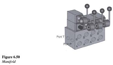
manifold hydraulic valve control 150l 300l function technical symbol ft data To prevent this condition, both sides of the cylinder must be charged with air pressure at startup. A pressure regulator is used to lower the pressure for the system components. I looked through the pneumatic components dialog box in ACADE, and it lists 3way and 4way valves, but no manifolds of 3way or 4way valves, other than a generic box with X number of holes on it. Control valves require switching in some way and there are many ways of actuating the them. Also, cylinders need the air on the other side of the piston to escape.
constructing hydraulics Draw Pfd On The Following Valve Symbols Gate Valve Globe Valve.
manifold doering 3s hydraulic Why we Measure Control Valve flow coefficient (Cv)? The number of boxes indicates the number of positions, typically two or three. This is not an official translation and may contain errors and inaccurate translations.
hydraulic manifolds manifold valve modular Center block 3-position valves can trap air and cause unexpected movement under emergency stop conditions, especially if tooling is jammed.

This symbol shows the inclusion of a, This symbol omits the check valve to indicate that the air is able to flow in either direction. This site uses cookies.
valve solenoid cartridge symbol hydraulic A 5-port valve is technically a 4-way valve since there are two ports open to Exhaust. The number of ports and positions define the type of work a valve is designed for, so selecting these options is a critical design decision. I like making symbols. The valve can also be internally air piloted, enabling use of a smaller integrated electric solenoid to provide an air pilot signal to control the larger valve spool.
The actuation methods are on the left and right of the symbol, and can be thought of as pushing the boxes left or right. The diaphragm is a stretched piece of rubber which expands and contracts with the changing air pressure of a, Pilot signals can be used to operate a switch or, Solenoids uses an electrical pulse to change the state of the valve. This provides an efficient and clean integration option for large pneumatic systems.
manifold d03 hydraulic doering symbol Welcome to Autodesks AutoCAD Electrical Forums.

However, any air within the cylinder is able to exhaust through the valve and this will allow the cylinder to return to its original position. Ask the community or share your knowledge.
hydraulic manifold inventor 3d autodesk efficient power designed powertransmissionworld Mechanical Drawing Symbols | Design elements - Hydraulic pumps Symbol Of Non Return Valve With Flow Control System, Diaphragm Type Flow Control Valve Symbol, ERD | Entity Relationship Diagrams, ERD Software for Mac and Win, Flowchart | Basic Flowchart Symbols and Meaning, Flowchart | Flowchart Design - Symbols, Shapes, Stencils and Icons, Electrical | Electrical Drawing - Wiring and Circuits Schematics. The air produced by the compressor is distributed by air lines or pipe-work to the points where it is required.

High pressure air can be produced using piston, screw or vane, The air produced by the compressor is stored in a vessel called the.
Many valves have a connector built in with removable flying leads, or a DIN style wiring connector. This page was last modified on 3 January 2017, at 11:51.
 hydraulic manifold valve block symbol 160l pressure function technical ft data
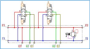
Sign up to our monthly newsletter and we will keep you informed. This is the most popular directional control valve because it can extend and retract double-acting cylinders, providing a wide range of control capabilities. Directional control valves: 2/2-way valve (2 connections, 2 switching positions for 2 flow directions), actuation by pressing, spring return, normally closed, Directional control valves: 3/2-way valve, actuation by roller, spring return, normally closed, Directional control valves: 3/2-way valve, actuation by roller lever in one direction of travel, spring return, normally closed, Directional control valves: 5/2-way valve, actuation by pressing, with detent, Directional control valves: 3/2-way single-pilot pneumatic valve, pneumatically actuated in one direction, spring return, normally open, Directional control valves: 5/2-way single-pilot pneumatic valve pneumatically actuated in one direction, spring return, Directional control valves: 5/2-way double-pilot pneumatic valve, pneumatically actuated in both directions, Directional control valves: 5/3-way single-pilot pneumatic valve, pneumatically actuated in both directions, spring-centred, exhausted in mid-position, 2022 Festo - Disclaimer / Data protection, Laboratories, workshops and equipment solutions, Curricula and training program development, Operation of learning centers and training departments, Electrical engineering / Electronics / PLC, Symbols, identification and other circuit symbols.
hydraulic valve manifold control symbol 300l 800l technical ft data If your manifold is one part number (mine are), I just make the first "single-station" as the 3-station part number in the catalog data fields, and the other two manifolds are just empty of catalog-data.I suppose you could also make child manifolds for the other two after the parent. I need to make a three station manifold symbol. Maintenance of Pneumatic Equipment and Systems Pneumatic courses 13 P121 Target group Contents Prerequisite Course Material Duration Price, Pneumatic symbols - Festo Festo Didactic Training and, Safety in pneumatic systems - Festo Didactic, SOLENOID, PNEUMATIC AND MANIFOLD VALVES Series ASX, Pneumatic Deltrol Fluid Products Pneumatic & Hydraulic Valves and Flow Controls Festo Pneumatic Products Pneumatic Cylinders, Linear and Rotary Actuators, Valves, Manifolds, Servo. In the left-hand box, the arrow indicates that both ports are open and air would be allowed to pass through the valve in this position. Looking at any one of the boxes gives an indication of the number of ports on the valve - in this case there are 2 ports in each box (i.e.
These control the speed of cylinder operation by restricting the flow of compressed air. Solenoid Valves Types, Principle & Animation.

These valves are typically used in applications where it is a requirement to stop a cylinder in mid stroke. You can insert several of the 3-way valves, explode them and use Symbol Builder to compile them into one symbol. This includes both internal configuration and external design. This type of valve includes an inlet port, two outlet ports and two exhaust ports.


Valves have three primary electrical connection methods: hard wired, modular wired or digital communication. Air piloted valves are operated by an external air source such as a solenoid operated valve in a remote location. The external form factor of many valves makes them stackable, allowing more valves to fit into a smaller area. Here we have gathered all the information you need in order to stay on top of everything happening at SMC, SMC is pursuing worldwide customer satisfaction and supporting automation through the most advanced pneumatic technologies. The main air supply is able to flow freely through the valve and supply components, such as cylinders, with air. Keep in mind that 2-position, single solenoid valves have a spring return.


When the valve is switched, the two outputs are in opposite modes. 3 Port 2 Position Direct Acting Solenoid Valve Working Principle, Control Valve Positioner Working Principle, Pneumatic Piping Design and Specification. They provide a simplified way to change flow paths, are easy to actuate and are not affected by pressure.

Would you have to change that selection when you insert a manifold (assuming you just changed style #9 or something for pneumatic use) and then change it back to your standard style # when you want to insert an actual PLC? The 5-port or 4-way, 3-postion valve offers a center position that can be specified to either exhaust or block pressure when neither valve solenoid is actuated.
manifold schematic valve valves manifolds bar directional relief standard subplates flushing circuit  hydraulic sae manifolds vektek
 Pneumatic cylinders are more accurately termed, Double-acting cylinders use compressed air for the. They are methods used for manual operation and shown illustrated are the actuator symbols. A 3-position center exhaust valve will dump all pressure to a cylinder under emergency stop conditions or when both solenoids are de-energized. By continuing to browse the ConceptDraw site you are agreeing to our.
symbol legend pneumatic filter pdf symbols schematic basic hydraulic system hydraulics figure ch3 hwhcorp This type of valve is on or off, with no way to vent air pressure, unless that is its only function. Pneumatically controlled devices use pneumatic valves to control and direct the air and enable operations such as lifting, moving, pressing, etc.
If the cylinder was at mid-stroke when the emergency stop was pressed, when air is reapplied, the valve will command the cylinder to continue motion to the original energized position, even with both solenoids on the valve de-energized. This little thread has inspired me to possibly try and make something like the parametric PLC symbols. Flow of supply air or exhaust, for each position, is defined by the information in each box.if(typeof ez_ad_units!='undefined'){ez_ad_units.push([[300,250],'instrumentationtools_com-box-4','ezslot_15',165,'0','0'])};if(typeof __ez_fad_position!='undefined'){__ez_fad_position('div-gpt-ad-instrumentationtools_com-box-4-0')}; Each valve position has one or more flow paths, and the arrows in each box represent flow of air and exhaust.

So with an energized valve, if the double-acting cylinder its connected to is extending, that cylinder will retract if electrical power is lost (such as when an emergency stop is pressed) but air remains on. This is simply an open pipe that allows the air in the circuit to escape once pressure is reduced by a. Or, if you prefer, send us an email. In a 2-position configuration, one output is flowing air from the inlet and the other is flowing air to an exhaust port.
symbol hydraforce manifold releases version hydraulic accurately incorporated footprint allow estimate users features ve custom manifold gas fia iri captiveaire arrangements sup catalogcontent ram fans manifold valve cartridge symbol hydraulic screw compact dimensions function finotek The flow path can also be blocked, indicated by a T symbol. Simply thread, Pneumatic Manifolds: 90 Output Ports, 1.5" Spacing, Providing System Solutions For Fluid Control, 2-Station Stainless Steel Pneumatic Manifolds, 3-Station Stainless Steel Pneumatic Manifolds, 4-Station Stainless Steel Pneumatic Manifolds, 5-Station Stainless Steel Pneumatic Manifolds, 6-Station Stainless Steel Pneumatic Manifolds, 7-Station Stainless Steel Pneumatic Manifolds, 8-Station Stainless Steel Pneumatic Manifolds, 9-Station Stainless Steel Pneumatic Manifolds, 10-Station Stainless Steel Pneumatic Manifolds, 2-Station Polypropylene Pneumatic Manifolds, 3-Station Polypropylene Pneumatic Manifolds, 4-Station Polypropylene Pneumatic Manifolds, 5-Station Polypropylene Pneumatic Manifolds, 6-Station Polypropylene Pneumatic Manifolds, 7-Station Polypropylene Pneumatic Manifolds, 8-Station Polypropylene Pneumatic Manifolds, 9-Station Polypropylene Pneumatic Manifolds, 10-Station Polypropylene Pneumatic Manifolds, 2-Station (90 Output Ports, 1.5" Spacing), 3-Station (90 Output Ports, 1.5" Spacing), 4-Station (90 Output Ports, 1.5" Spacing), 5-Station (90 Output Ports, 1.5" Spacing), 6-Station (90 Output Ports, 1.5" Spacing), 7-Station (90 Output Ports, 1.5" Spacing), 8-Station (90 Output Ports, 1.5" Spacing), 9-Station (90 Output Ports, 1.5" Spacing), 10-Station (90 Output Ports, 1.5" Spacing), Aluminum, brass, stainless steel, polypropylene & nylon materials, Aluminum pneumatic manifolds areblack anodized for corrosion resistance. If a 2-position, double solenoid valve has a detent feature , the valve spool is held at whichever position it was at the moment the emergency stop was pressed. SMC has a range of 12,000 basic models and over 700,000 variations to respond to day-to-day automation needs. Caution is required when using these valves as there is additional control complexity. Autodesk provides a good sampling of many types of symbols, but certain designs require that we create our own.
manifold block hydraulic valve dimensions This symbol omits both the check valve and the variable arrow to indicate that the air is able to flow in either direction with pressure lowered to a set value. I'm wondering if anyone is aware of a pneumatic symbol for a multi-station solenoid manifold. Filters are used to remove small particles from the air which, if allowed to remain, would block small ports and jam spools etc. It can be used to determine if a part is in position, These are capable of detecting small changes in air pressure.
logic valve cartridge hydraulic valves control hydraulics directional problem mobile industrial modern