This is the classic Kouhoupt model. You can add something to the other side of the wire that is sticking out of the popsicle stick or just bend it so it doesn't slide out. The Swedish navy has built a line of stirling powered submarines, or air independent propulsion submarines. I heated up the tube and cap, hoping the solder would melt inside and wick up into the joint. It is a matter of polishing and testing frequently until you get the required t; patience is a must for this process. Any source of heat will make it runIve even seen one running on dry ice. Required fields are marked *. Plus, well give you access to some great CNC reference materials including: Just enter your name and email address below: Your email address will not be published.

Check to make sure that the piston is relatively air tight but can still mover freely. That material might have been better utilized providing increased heat transfer area. You can use super glue, JB Weld or hot glue, for this part. Last year I was an IB student in the MYP program. Alphonse Vassalo: Many finely crafted Stirling models including a 4-cylinder. Edward Bashauers Stirling Airplane Engine, Alphonse Vassalos Solar Stirling with an 18 Mirror, Alphonse Vassalos Backwards Stirling has the hot section in the middle, Blazer is a Duclos-designed Flame Licker by Roy Rice. This method produces a ywheel which runs nice and true on the nished engine. The gas inside expands rapidly, rises through the plastic pipe to the top of the acrylic cylinder (B) and pushes the drive piston (C) down. In Ironman movie,small and portable size arcreactor is that possible??? Stirling was born on October 25 1790. This company sells airpots ready to go. These all came from sites in the links above. I have no trouble with soft soldering as it is so much more controllable. I noticed that at one point in the revolution it seemed tighter than normal and it was my guess that this extra friction was enough to stop it from running. Practical Stirling Engines employ several tricks. Aquatap is a Ringbom Stirling by Roy Rice at Stirling South. You may have to trim off some of the aluminum to allow the popsicle stick to sit flush to the plastic bottle. Acrylic (or Perspex) will polish up really quickly and easily with a bit of Brasso on a rag. Those are the most common problems I have encountered. Now that we have all our pieces, we can put it together. Roy UKs Stirlings: Several to choose from made from simple materials. While that is curing, take the other aluminum sheet and find the center and drill a hole for the 1/16 ID beats pipe. 6. Thank you. I got a lot of good information from this site: http://diystirlingengine.com/. Get in touch with The Sheds commercial team here., Sign up here to The Shed monthly email newsletter for exclusive reader offers, Split aluminium mandrel with tapered screw, 10. It does take quite a bit of parting-off to plunge the lathe cutting tool deep into the workpiece so lots of cutting uid is required. With hard soldering, I dont like seeing the nice shiny parts Ive just made oxidizing badly as they are heated to high temperatures. Lucid explanation, now I know what is Sterling Engine. The engine runs at about 600 RPM with a good differential between the hot and cold ends of the displacer tube. then cut through the can so that you get a single sheet of aluminum. Aimed at those with a few tools and perhaps a few clues: this is the magazine for real sheddies. To add a professional nish to the edges of the base, I routed them with my favourite cutter. I use a home-made tapered screw to clamp the workpiece securely. This part was quite difcult to make because the kit came with just enough material for the overall length.
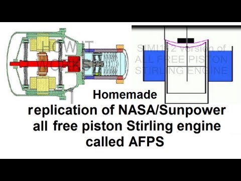
Get our latest blog posts delivered straight to your email inbox once a week for free. 5. There was nothing to hold in the chuck; so a bit of extra material would have made the task so much easier.As it was, I had to make another split mandrel to try and hold it but it was very difcult to get any drive to it while cutting those ns. I like the styling, Another ridiculously cool Bohm model! Make a low-pressure, hot air engineBy Ross Purdy. 12. It would be great if people would refer to this type of Stirling as the "Senft engine" to give credit where credit is due. If you get confused refer to the pictures and it might make more sense. You can usually buy several rolls for a dollar, and it can be used to reduce friction in several locations. Cut out 2, 1x1 inch squares from the balsa wood. by Bob Warfield | Blog, CNC Projects, DIY CNC | 0 comments. They could burn any fuel that they wanted including diesel and even jet fuel. I replaced it with a 3 mm silver steel rod. The easyo ux is a liquid paste and you brush a small amount along the joint. However, according to a quick look at Wikipedia, "A Stirling engine is a closed-cycle regenerative heat engine with a permanently gaseous working fluid". You can buy this in a syringe commonly used for rework and repair of circuit boards. Im also interested in larger Stirling designs for the production of electricity from solar power. Hi, Nice work! At the end of the year we had to do a research project on something that interests us.
I have made three very low temp diff. Participated in the Full Spectrum Laser Contest 2016. I think my brother was trying to make that type of model last year (It didn't work though). Stirling South: Nicely made CNC Stirlings from some college professors. Low Temperature Difference Stirling: Run a Stirling just by setting it on top of a steaming mug of coffee. I did a tiny bit more polishing of the bore with the Dremel wheel and Brasso xed that problem.The piston/conrod assembly was then xed to the crankshaft and tested on the main bracket with the acrylic cylinder. I thought it must have been in the rod and sleeve although that also seemed ne. He and Dr. Ivo Kolin at the University of Zagreb back in the 80's had a friendly competition to see who could build a Stirling engine that ran on the smallest difference in temperature. Heat is applied at one end to the displacer cylinder (A). I guess the idea of using the thin-walled tube was to keep its thermal mass low. Then mark the point just over the displacer rod on the wire and again 1/8 inch on either side. Dont let the theoretical charm of the regenerator get in the way of the engine. They are the newest diesel electric subs that can stay underwater for several times longer than other diesel electric vessels, something only nuclear subs could do. There are larger scale solar farms in Arizona that produce power using stirling engines. The engine looked like it wanted to run but would do less than one revolution and stop. Use of thin wall tubing and making the chamber walls out of something that doesnt conduct heat so well (although it has to conduct the heat into the chamber, just not along the chamber longitudinaly) is also helpful. Cylinder head, air port The drive cylinder head and air port were straightforward parts to machine and were soft-soldered together using my heat-gun method. Then glue the radius lengths perpendicular to the first pieces of wood so that they sandwich the copper pipe, on to the aluminum. The Hermits Machine Shop: A few Stirlings similar to Rudy Kouhoupts including a Stirling fan. I am surely gonna try and build this one. Make sure that it has very little friction, with some oil, gravity should be able to move it all 2 inches of the pipe. A neat illustration of the engine and the story behind it is here: http://www.animatedengines.com/ltdstirling.html. Hook one loop onto the 90 bend on the displacer rod and lift the displacer about halfway up. These were a simple turning job in the lathe.My secret to professional soft-soldering is electronic solder paste. Thank you for posting, Question The next step is usually lots of elbow-grease to clean and polish the workpiece back to its former glory. This is then tted to a shaft running true in the lathe and turn the reverse side and over-all diameter. Take your chopsticks or dowel and cut 4 pieces, 2 the diameter of the aluminum and 2 the radius of the aluminum. Bend the end of the wires inward, this will help the wire anchor into the epoxy later. Hence forth this part will be called the displacer. Chuck Fellows built this very nice vertical Stirling, An interesting and attractive Stirling that reuses an old OS model airplane motor, Beamer is another nicely detailed engine by Syl, A 3-Phase LTD Stirling built as aresearch project at UC Berkeley, Nice looking Stirling, apparently from a kit sold byForrest Classicsand made by Bohm. length of displacer chamber L = 3 times its diameter. First, I sand with some 800 grit wet & dry then move up to 1000 or 1200 and then nish with the Brasso to get it back to crystal-clear again. You gotta love the Steampunk + Raygun motif. Awesome Instructable, even though I did have to look up what an IB in a MYP was ;-). Jon Bondy: Has built several model Stirlings, has a Stirling design program on the site, and keeps octopus and cuttlefish as pets. Jan Ridders Modelbouw: Many interesting engines on display, and he will send you plans too! Since the engine runs on the rapid heating and cooling of a working fluid, it is important that there is a high temperature gradient. But twice the power means twice the heat energy in and out. These days electronic circuit-board components are soldered with a lead-free solder paste which consists of tiny solder balls in a ux. Second, wherever possible, minimize the mass (weight) of the moving parts. So the problem had to be in the sliding yoke. Trace 2 circles on the aluminum sheet using the rest of the plastic bottle as a stencil and cut the circles out, just outside the lines you marked. Not sure about other sizes. (https://www.uwrf.edu/MATH/EmeritiJamesSenft.cfm) Dr. Senft (who is also a great machinist) was a real inspiration to me as a teenager, through his books and articles in Live Steam Magazine. Bill Sondagh of the Netherlands has a fine collection of Stirlings he has built. Cut a 3 inch piece of steel wire and make a small loop in the middle of the wire big enough to let another piece of wire pass through. Next project in the pipeline!! The rod with the kit was an odd size (around 3.1 mm) and was scored with a spiral the entire length. After all, I wanted the 0.5 mm thickness with respect to the inside, not the outside, of the pipe. Although it had great design and much thought had been put into the engine, the engines Stirling and his brother built tended to be unreliable because of some of the material limitations and the steam engines started becoming more reliable and safer. The ideal expansion ratio is the square root of the ratio of average absolute gas temperatures taken at the hottest and coolest points in the cycle. The Stirling engine is safe, unlike steam engines, runs on low pressures and can be made quite efcient (up to 40 percent). Same here. With the world taking a new focus on "green" energy, the stirling engine is making a comeback, being used in generators on small scales in remote areas and in larger scales, contributing to power grids.The next few steps will get more into the history and applications of stirling engines.If history and long boring back stories aren't your thing skip over to the build at Step 4. I would only add two things to the suggestions presented by TedRees and others. The second secret is to heat it with a hot-air, paint-stripper gun on a re-brick until the solder melts and ows around the joint. I unscrewed the pen tip, removed the felt, rinsed out the ink with meths. Stirlings 1815 design used the following ratios: The purpose of making the heater chamber longer than the cooler was to maximize the temperature differential between the two. Minimize dead volume. In the internal combustion engine, the explosion does all the work. I go for two or three top coats with a light sand between each coat. The internal bore was polished using a Dremel with a 12 mm felt polishing wheel and the bolt holes were done with a pipe cleaner soaked in Brasso.After all this polishing work, two aws in the piece of acrylic supplied with the kit became evident. You just have to bore both holes at the same time so they end up parallel to each other. Syls Hobby Page: Lots of engines and other HSM projects. HIgher pressures also require more material to contain the pressure. The piston is screwed onto a long rod which is driven by the main crank-shaft. Piston I turned the piston down to almost the correct size, measuring with a micrometer as I went. After about 30 seconds, I gave the ywheel a ick and presto, away it went. I have tried multiple times to build one of these stirling engines using various designs and instructions. Using steel wool, sand paper or a rotary tool, polish the pipe, especially on the inside. 14. mix a small batch of 2 part epoxy and fill the glue stick cap.
Fascinating devices, no? This is easy to buy in crystal form from the supermarket and does a good job of cleaning up copper, brass, and steel. Minimize aerodynamic losses. His patent focused on some parts that kept some residual energy within the system allowing it to require less energy and therefore less fuel. swept volume of displacer = 1.5 times swept volume of piston cylinder. 11. Your email address will not be published. length of displacer = 2/3L and stroke = 1/3L. then take more JB Weld and glue it to the sides of the chamber so that they are on opposite sides and line up with the 3/4 inch pipe and the 1/16 inch pipes. Graphite is also useful for this, or Silicone lock lubricant. The cylinder then had to be hard-soldered squarely onto a ange at one end and a cap to the other. The heated air expands and pushes the piston out, turning the wheel, 3. When the piston was a tight t in the bore I began polishing the outside of it with 1000 grit wet & dry paper wrapped around a at bar. a general rule of thumb is that gravity should be able to pull it down with relative ease. The Stirling engine how it works The Stirling engine is a fascinating engine that magically converts an external heat source into rotary motion. The high silver-content solder-sticks I bought to do the job are more expensive but make the job easier as the melting point is lower. I removed the crank-pin 5BA bolt and tried it in the yoke slot, thinking maybe it was when I soldered the yoke together that I didnt get the two sides parallel. Remember the piston has about 1.5 mm clearance around the bore, so no special tting is required. Using steel wool or sand paper, take off all the paint and clear coat on the aluminum sheet. I put a tiny amount on the parts that need to be soldered together and remove any excess. I wasnt happy with the look so I made a whole new piece from an offcut of plastic. Some tricky soldering remained but nothing that needed precision tting. I have been to the point where I just want to hurl the thing against the wall. Finally you can attach the flywheel to the end of the shaft by sliding the shaft through the holes in the balsa wood, bending the wire 90 and use super glue to glue it to the flywheel. The Ringbom requires no mechanical linkage between the two chambers. To power these things, you can apply hot boiling water to the bottom side, let it heat up for a moment and give the flywheel a spin. Make sure to oil/grease all the joints and that it runs smoothly when you turn the flywheel.