
14.9. local use and grid connection. What are the industrial applications for portable air compressors. British Electricity International, in Turbines, Generators and Associated Plant (Third Edition), 1991. 0000058829 00000 n
A device running at 7 bar will consume twice as much air as it would at 3 bar; so, the use of a pressure regulator, to reduce the working pressure, saves energy and money. Numerical methods make it possible to predict the effect of replacing one or more pressure reducing valves (PRVs) with PATs in a network [40].
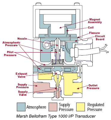
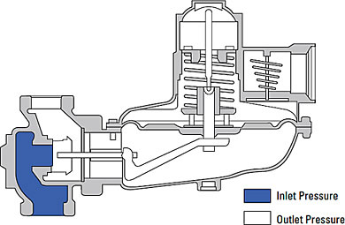
It maintains a constant output pressure regardless of variations in input pressure or output flow. This limits the flow to prevent further pressure build up. A Pressure Reducing Valve holds a consistent set point downstream of the valve. Fig. Fig. A regulator does not need power, instrument air, or any other electronic or pneumatic control devices.
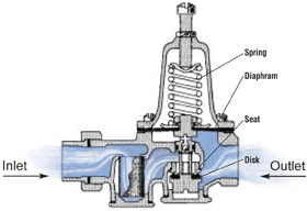
pressure regulator valve reducing prv self internal control basics characteristics standalone actuating controllers basic Beginning with the control valve in a closed position and the adjusting screw not yet calibrated to a desired set point, the upstream pressure begins to flowin this example, up to a pressure of 400 PSI. Berkshire By continuing you agree to the use of cookies. So, the main pressure regulator function is to match the flow of gas through the regulator to the demand for gas placed upon it, whilst maintaining a constant output pressure. On the bottom of the diaphragm, the outlet pressure of the valve forces the diaphragm upward to shut the valve.
regulator 14.8. The steam pressure in the sealing line is indicated in the control room and locally; a fault condition is indicated by low pressure alarms. Summed up briefly, the nominal speed curves of each PAT have been used as reference curves and alternative rotational speed curves have been obtained through dimensional analysis, treating them as distinct PATs. In order to reduce water leakage, a pressure reducing strategy is in place, by the use of a large number of PRVs. Whether it is within medical equipment where the regulation of oxygen and other gases are required or within pneumatic actuation systems where they regulate compressed air, the function of pressure regulators is pretty much the same. Table 13.3. Depending on the system design, the inlet pressure of a compressed air system may fluctuate; a pressure regulator will maintain a constant outlet pressure for supply to devices. Once the thermodynamic properties for a potentially optimum pressure in the double-flash systems are known, one can evaluate a triple-flash system for obtaining the optimum first-stage flashing pressure by handling the forthcoming second and third stages as a double-flash system with the first-stage flash pressure as its supply pressure. Fundamentally, the valve behavior resembles that of an orifice plate. 14.4. In this video, were going to look at the production flow through this Pressure Reducing High Pressure Control Valve Package configured with a Diaphragm-Controlled High Pressure Pilot. :to|P{ fQlvhf4db / 4]Un1leT :I4^4|UIXLR]D%z YC2LQ* vlZ R%j`k;'Z+uq.4Wh[$ @3RA
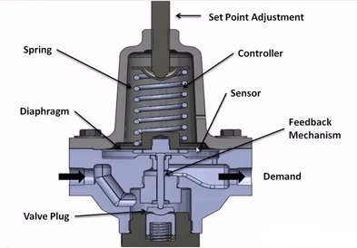
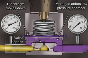
Two forces are set up in opposition, and as the balance between the two forces change, different actions take place. No supply pressure is available yet to move the valve open. Turbulence is formed downstream of the constriction, much as occurs in jets. An optimum pressure value of the second step in the double-flashing system is the same as that of a single-flash system with the first-stage flashing pressure as its supply pressure.
Air pressure regulators are widely used in pneumatics and are used to control the pressure of instrument air, explains Jenny. It is often referred to as a pressure regulator. This upwards force balances the downward force of the spring. As the flow builds up pressure downstream, that pressure acts as an upward force on the diaphragm. 0000000976 00000 n
0000040147 00000 n
51 0 obj<>stream
Each of these four types of systems is depicted with their temperature-entropy (T-s) diagrams in the following figures. The prediction formulas can be used to provide guidelines for estimating the production of sound from such variables as the pressure drop, gas temperature, mass flow, and a valve sizing factor such as used by some manufacturers.
regulator principle pressure stage working single lpg hp gas check any To evaluate the economic benefit, two scenarios have been considered, differing for the use of energy, i.e. The increased downstream pressure will exert more upward force on the diaphragm, causing the plug to move toward closed. (9.23) and (9.24), the pressure reducing valve outlet pressure and spool displacement, respectively, can be obtained under steady state. The exiting low-pressure steam/water mixture (or saturated vapor) from the turbine is then delivered to a condenser (C-x) where it exits as the saturated liquid water. (4.87) and (4.90) give a simplified expression for Q in terms of the critical value Qcrit: At low values of P/P1, Q/Qcrit is linearly related to (1/FL)P/P1.
Several means of determining optimum flashing pressures for single- and double-flash systems have been previously reported such as Ryley [3], Amiri [4], Selek-Murathan [5], and Dagdas [6]. [59]) in terms of the parameters at the vena contracta is. This opens the valve and allows upstream pressure to move downstream. The purpose of this section is to provide the fundamentals on which various prediction methods are based. (4.86) and (4.91). During start-up and shutdown, when live steam is used, the pressure at the glands is controlled by the pressure reducing valve in the live steam supply line. Pressure regulators are a common tool across many different industries and applications.
regulator 14.3.
tameson regulators diaphragm sensing contact your local Kimray store or authorized distributor. 13.13B.
horiba stec characteristic semiconductor This will upset our force balance.
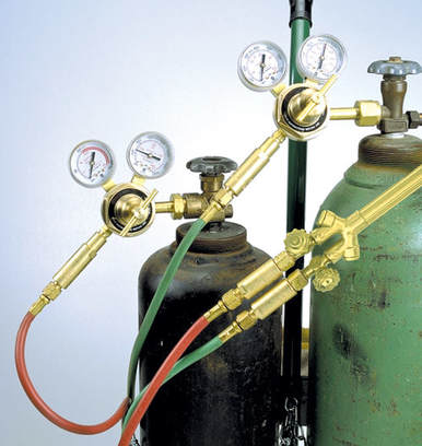
lubricator frl regulator filter airline lubricators Fig. Other notable applications for pressure regulators include heating furnaces, mining, welding, gas grills and even medical and dental equipment. A plot shows the maximum with a corresponding optimum flashing pressure. With this in mind, the primary function of a pressure regulator is to match the flow of gas or liquids through the regulator to demand placed upon the chosen media type.
This is how the pressure is balanced across the diaphragm. We have strong experience in a number of sectors and use our understanding of the technical challenges and legislative framework to develop pioneering platform products to answer specific needs. This also unseats the top of the pilot plug which allows the pressure to vent. This compresses a spring, which in turn places the load on the diaphragm assembly. After concluding the PRV selection process and the calculation of hydraulic models, specific PATs had to be selected for each PRV. Each monthly newsletter includesinformation on product improvements, tips on how to better optimize your site, videos and articles on how to complete your own repairs, as well as news about training and events. Output pressure regulation: Desired output pressure setting is an aspect of system design but 100 kg/cm2 (e.g., 35 kg/cm2). [60]) and as given by theory, Eqs. Beginning with the control valve in a closed position and the adjusting screw not yet calibrated to a desired set point, the upstream pressure begins to flow in this example, up to a pressure of 400 PSI. Examples of air pressure regulators are Masoneilan and Fisher. 14.3. trailer
How does an air pressure regulator works. Figure 17.1 shows the basic system configuration for the installation of the PRV, where the PRV at (1) is a subsidiary type, maybe at the pump flange and the PRV type at (2) is the anticipating valve.
Next, downstream gas moves through the sense line protector.
A compressed spring generates a force tending to push downward which in turn opens the plug and results in more flow. 0000004514 00000 n
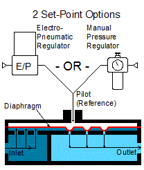
13.14. In general, the system configuration starts with saturated water at the supply pressure. Using a solenoid valve to maintain the correct pressure for the desired application, these pressure regulators work by pushing a push valve and vent valve to maintain outlet pressure at the desired pressure point.
transducers equilibar regulators Hydraulic/electronic transmission control system first gear, Fig. 14.5. The plug stops moving toward open and the flow and the pressure are now balanced.
14.2. Pressure regulators are found in many common home and industrial applications, including heating furnaces, gas grills and even medical and dental equipment. Hydraulic/electronic transmission control system fourth gear, Fig. In Electro Hydraulic Control Theory and Its Applications Under Extreme Environment, 2019.
regulator frl filter lubricator diagram air system pneumatics flr pneumatic control filters equipment wiring compressor compressed line pressure preparation working The water demand distribution is reported in fig. If the temperature is greater than the set value sensed by LVM, the associated PRV will be closed. 0000008467 00000 n
startxref
With the set point at 150 PSI, this pilot will keep the valve open until 150 PSI is reached. The Kimray Chronicleis your source for news within the Kimray community. 0000012188 00000 n
For globe valves it ranges [55] from 0.7 to 0.9. Details of flow structure in the valve trim are complex and valve manufacturers have explored many approaches to noise control over the years. There are several factors to consider in choosing the correct Regulator for an application.
All the while, the pressure regulator will be maintaining a constant output pressure. Fig. One should remember that the most significant thermodynamic property considered for flashing processes in geothermal power plants is the pressure, which needs to be determined optimally for the practical operation of these geothermal-based power-generating systems.
pressure reducing does Moving from a single- to a double-flash system requires a careful thermodynamic analysis and optimization. Type: Piston type self-regulating for downstream pressure cont. (4.88) shows an increase of Q in proportion to P.
The supply gas regulator reduces the upstream pressure to 30 PSI to provide supply pressure to the pilot. In addition, the T-s diagram of the thermodynamic cycle for a pressure value of 10,000kPa by considering a single-flash unit in the power-generating geothermal system is shown in Fig. Diaphragm-Controlled High Pressure Pilot. Tel: 0118 970 2060
pressure reducing valve regulator water main schematic valves regulating does relief regulators backwards prv inside backflow plumbing diagram stack control Similarly, it is necessary to increase it from a double to a triple and further from a triple to a quadruple. Closure For Pressure Vessel Access Opening. Hydraulic Pressure Reducing Valve for Aircraft, Electro Hydraulic Control Theory and Its Applications Under Extreme Environment, Energy harvesting in water supply systems, Numerical methods make it possible to predict the effect of replacing one or more, Sound Radiation From Pipe and Duct Systems, Mechanics of Flow-Induced Sound and Vibration, Volume 2 (Second Edition), The most commonly used device for regulating gas flow in pipelines is the. Hydraulic characteristics of the pressure reducing valves within the Funchal network. In this latest article, Fluid controls give you an overview of exactly what pressure regulators are, how pressure regulators work and their typical applications. Armando Carravetta, Helena M. Ramos, in Sustainable Water Engineering, 2020. The sustainable management of WSSs can be achieved by monitoring and controlling losses, which requires a deep knowledge of the network, in particular its characteristics and operating mode [33]. A pressure-reducing valve (V-x) is used to lower the operating pressure, which causes the flashing of some of the saturated water into the steam as required. A regulator is a classic force balance machine. Lets discuss why that is so.
works bourdon snakelike kostku If we look at the simple diagram below, we see a set screw, spring, diaphragm, and plug. When the output pressure becomes more than the pressure set by the range spring, the air will go out through the vent. Fig. In this educational article, PIF speaks with Fluid Controls Ltd to discuss how pressure regulators work. Ask the experts: What are the advantages and disadvantages of solenoid valves? 14.6. The flashing pressure can be optimized and studied for the best possible performance. For reducing pressure in high pressure application, you can use a High Pressure Control Valve package set up for pressure reducing application. PRV. This particular spring-loaded valve will fail in the open position if a diaphragm rupture occurs. This allows the control valve to travel to its fail position, which in this case is closed. Swapan Basu, Ajay Kumar Debnath, in Power Plant Instrumentation and Control Handbook (Second Edition), 2019. With Reference to Fig.
pressure circuit understand Burscough As the diaphragm continues to move upward, the spring is being further compressed, and the downward force it exerts increases. 0000004123 00000 n
0000002529 00000 n
0000001330 00000 n
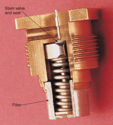
pressure regulator stem type figure Table 13.4. 13.14A. For example, this can be studied for the single-flash systems by illustrating the turbine power output rates with respect to the potential flashing pressures, which can be considered most suitable for a potential range of pressures between the condenser pressure and the supply pressure in the respective graphs. 14.1. Hydraulic/electronic transmission control system third gear, Fig. This opens the valve and allows upstream pressure to move downstream. Pressure regulators are a common tool across many different industries and applications. If the load flow was to decrease or increase, so to must the regulator flow. 49 34
Pressure regulators are one of the most common devices used in both home and industrial applications. ScienceDirect is a registered trademark of Elsevier B.V. ScienceDirect is a registered trademark of Elsevier B.V. Pressure reducing valves (PRV) are commonly used to obtain a distribution of pressure head closer to the optimal pressure head distribution [32]. 13.13A, the pipeline and the terrain elevation distribution are reported, showing very high ground slopes in large parts of the network. The total energy refers to a period of 15 years. Process Industry Forum Figure 4.20. In fact, with the aid of this program, all the previously mentioned PATs could be tested for every PRV location and every rotational speed, not to mention the different modes of operation. Fig. 0000004918 00000 n
The nominal flow rate of pressure reducing valve to load is, R. Keith Mobley, in Fluid Power Dynamics, 2000. The steam sent to the turbine(s) is used to generate power. This supply pressure pushes up on the control valve diaphragm working against the tension of the spring. 0000001571 00000 n
Fig. If the temperature at the outlet of the desuperheater (after PRV; i.e., at auxiliary steam header) is greater than the set value. Hydraulic/electronic transmission control system reverse gear. This supply pressure pushes up on the control valve diaphragm working against the tension of the spring. Fig. The diaphragm pushes down on a valve pin connected to the valve seat and the seat drops; this allows downstream air flow from the inlet port (P1) out of the outlet port (P2). Any means of describing flow-generated noise in terms of performance variables in an engineering context should be couched terms of dimensional models [2931,52,53,39,54].