
Select the maximum and minimum temperature within the allowable range;Select water-proof solenoid valve in the environment of high relative humidity and raining;Select special solenoid valve like marine solenoid valve in the environment of vibration, jolt and impulsion;More items Solenoid valve has 2 wires (normally closed) Treadlite foot switch Can someone draw up a wiring diagram from 110v power cord Up to 3 valves can be manifolded together.
valve spool diagram valves solenoid air internal pneumatic control flow direction controlled mechanical graphic zaworu dryers fittings Vertical. Wiring of the solenoid valve is simple. 2-1/2" Bolt Spacing 91-93 models only Blown fuse link in wiring harness It also shuts off with the key and helps prevent the engine from backfiring which can cause damage 5DKDFJ Generator Fuel Shut Off Solenoid: PeteBeau: RV Systems & Appliances: 1: 07-30-2016 08:00 AM: Cummins B & C - Series Fuel Shut Off Solenoid: rwinslow: Cummins Engines: 3: 11-18-2014 D03 & D05 SERIES 35- SOLENOID VALVES NFPA SIZE: D03 & D05 31341 Friendship Drive, Magnolia, TX 77355 Tel. CAUTION Dangerous hydraulic pressures may develop if a hand valve is EO 1.4 IDENTIFY the symbols used on engineering P&IDs for the following lines: a. The diagram below shows a standard hydraulic wiring schematic.
hwh irv2 forums 42ft 525hp vicksburg c13 27 12 Volt Solenoid Wiring Diagram - Wiring Diagram List (Helen Cooper) Windshield wiper motor Hydraulic unit Hydraulic unit Waste gate solenoid valve Air flow sensor Front speed sensor (LH) Control harness and front harness combination. Below are wiring diagrams for pumps used on bale spikes and dump kits. S3) Electrical System approximate values: Solenoid Valve Coil Resistance = 6.
Solenoid Valve (Red Wire coil valve hydraforce series 24v solenoid dc leads wire diagram Pressure of air supply symbol. Initially, disconnect both terminals of your car battery. Then, remove the faulty starter relay by unbolting it from the engine bay and replacing it with your new relay.Next, identify the wire from your starter solenoid and connect it to one of the big terminals of your new relay. More items Hydraulic solenoid operated selector/diverter valve. A Sol.
solenoid diagram valve hydraulic wiring gas symbol PN#: VP1135R.

Torque fittings to 18 lb-ft. 2.
valve solenoid diagram hydraulic wiring gas simple sample The diagram shows a winch powered by a hydraulic motor. These valves are also known as cartridge valves, and they screw into your mounting block.. Place three-way valves between the pressure source and a single-acting cylinder.

To ensure the peak performance of a solenoid valve, it is essential to install the valve properly.
controlled Vickers Solenoid Valve Wiring Diagram,Solenoid.Download Free Printable. They usually consist of a spool inside a cast iron or steel housing.
hydraulic solenoid valve gas diagram wiring valves schematic dual heater troubleshooting control circuit fire service stage honeywell low shows figure Symbol for spring or rest position of valve. Check out this guide to finding the right industrial solenoid valves for your business so you can order your solenoid valves today.


Complete workshop & service manual with electrical wiring diagrams for Caterpillar 247B, 247B2, 247B3, 257B, 257B2, 257B3 Multi Terrain Loaders. Note 4 and 8 type spools are always V. Solenoid energization identity is independent of mainstage porting.

CAUTION Dangerous hydraulic pressures may develop if a hand valve is
Solenoid Valves - Parker Hannifin The spring pushes from the side that is drawn on and will return the valve back to its failsafe position. 3. wiring diagram ego scion xb tc ford brz switch subaru stereo 528t twist toyota relay fr override circuit which gt.
Hydraulic Solenoid Valves | McMaster-Carr 
"Directional control valves route the fluid to the desired actuator. Start and stop flow with an electronic signal. For instance , when a module will be powered up and it sends out the signal of fifty percent the voltage plus the technician will not know this, he would think he has a challenge, as he would expect the 12V signal.
110v Solenoid valve wiring help Solenoid Operated Directional Valves - Hyvair Corp. Motor valve operator c. Solenoid valve operator d. Piston (hydraulic) valve operator e. Hand (manual) valve operator f. Reach rod valve operator EO 1.3 IDENTIFY the symbols used on engineering P&IDs for educators and ejectors. Rugged four land spools. 68710 66467 66132 68375 66026 65887 98250 93943 68388 68389 5603910 68711 68730 85510 68093 Please see Battery Cable recommendation page 3 for proper cable length to use for your hydraulic power unit.
Hydraulic Solenoid Function - Wood-Mizer Various types of Solenoid valves and their schematics solenoid valves hydraulic diverter valve They are usually operated in the open position and are used to start/stop the flow of gas/liquid. 12 volt DC voltage.
Bucher Hyd. Models Solenoid Wiring Instructions - YouTube Schematics and Flow Diagrams - HWH Corp Valves The red [#z) and orange (#4) wires complete the circuit for valves with solenoid b. Double solenoid valves, two position, detented Single solenoid valves, solenoid at port A end Single solenoid valves, solenoid at port B end PT AB Sol. A wiring diagram is a streamlined standard pictorial representation of an electrical circuit.
Valve Wiring Diagram Remove the ten T40 bolts securing the
valve body to the transmission. To properly read a wiring diagram, one offers to find out how typically the components inside the system operate. e47 diagram wiring plow meyers snow pump hydraulic meyer. Only the spool and valve body are shown. Phosphate finished body. 11 Images about 32 3 Way Solenoid Valve Diagram - Wiring Diagram Database : Solenoid Valve Technology | Emerson US, 12v Hydraulic Power Pack Wiring Diagram Download and also Double Solenoid Pilot - 5/3 - BSPP | AIGNEP USA. They can be connected in a normally open or closed position, therefore, there is a spring to return it to its norm Solenoid-Operated On/Off Screw-In Hydraulic Valves. The directional control valve with built-in relief features optional flow control to control the speed of the winch .
Hydraulic Solenoid Wiring Diagram solenoid valve hydraulic diagram wiring control valves basics relief system repair systems. The spring symbol defines the at Rest position of the solenoid valve. hand lever, solenoid armature, etc.) Hydraulic Room Extension Schematics & Flow Diagrams. 13.2 GPM @ 3600 PSI. For instance , when a module will be powered up and it sends out the signal of fifty percent the voltage plus the technician will not know this, he would think he has a challenge, as he would expect the 12V signal.
Hydraulic and Pneumatic P&ID Diagrams and Schematics Solenoid valves Vickers Overhaul Manual Directional Controls Hydraulic Valves Spool Diagram.
valves wiring diagram Each and every one of these ideas are illustrated with sensible examples.
wiring solenoid The time taken for the main steam valve to move due to delays in the hydraulic pilot-valve and servo-motor systems is appreciable, 0.2-0.3 s. It is redesigned to accommodate a new governor body and different hydraulic circuitry. solenoid valve wiring diagram - Aprilaire Model. Title: D03, D05 and D08 Solenoid Valves.pdf Author: marcus.kennedy Created Date: 12/2/2010 9:42:13 AM Keywords ()
.
Solenoid Valve Installation | Tameson.com 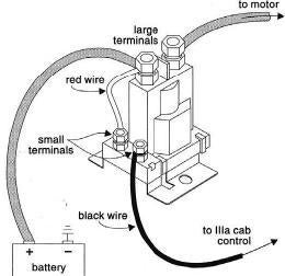
 plow wiring western diagram solenoid relay hydraulics snow plowsite unimount wire cable mark snowplow motor pump system edited dec 2009
 A solenoid is nothing more than a coil of wire designed to produce a magnetic field when energized. BLACK BLACK WHITE GREEN CORD GREEN 6 15 ADVANCE COIL RETRACT COIL 3 15 Part List For Solenoid Valve Assembly 3 Way/4Way QTY. ISARMATIC HYDRAULIC UNIT PARTS DIAGRAM End Cap Motor Motor.Find Western Plow Solenoid on sale right here with the biggest option of Western Plow Solenoid anywhere online. Flows to 22 GPM depending on spool.
 wiring diagram valve solenoid hydraulic lovely
 Back to Table of Contents M-3541
wiring As shown, the high pressure hydraulic fluid is being routed from Port 1 Hydraulic Solenoid Valve Wiring Diagram Sample wholefoodsonabudget.com. Please see Battery Cable recommendation page 3 for proper cable length to use for your hydraulic power unit.
wiring asco diagram solenoid valve redhat enchanting pattern Symbol for pressure inlet port of valve. 2.5 amps.

Loss of connection on the block will cause For the hydraulics to function properly the 48re Valve Body Diagram wiringall.com.
Hydraulic Solenoid Valve Wiring Diagram  Solenoid Valves Wiring
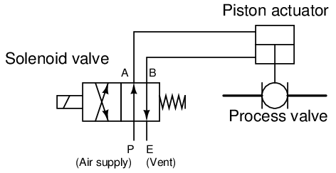
 Attach the spacers to the valve to maintain the appropriate fitting length even if you do not use the installation bolts provided to add on modular valves. A and B are two working ports, P is the pressure port and T is the return port.
Diagram Wiring 139-1982 = CSA Porting pattern according to ANSI B93.9 6) = AN 19 Without locating hole no code With locating hole and locking pin ISO 8752-3x8-St /62 E-47 Hydraulic Pump Diagram www.alamia.us. Includes a plumbing and wiring schematic.
 Solenoid Valve Symbols gas solenoid valve wiring diagram
 The red [#z) and orange (#4) wires complete the circuit for valves with solenoid b. Vickers Solenoid Valve Wiring Diagram,Solenoid.Download Free Printable. Hydraulic cylinder schematic circuit control read valve drawing diagrams hydraulics reading fluids report examples assembly activation.
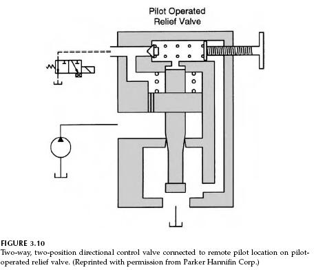
valve hydraulic pilot operated relief diagram valves wiring solenoid circuit circuits 2-1/2" Bolt Spacing 91-93 models only Blown fuse link in wiring harness It also shuts off with the key and helps prevent the engine from backfiring which can cause damage 5DKDFJ Generator Fuel Shut Off Solenoid: PeteBeau: RV Systems & Appliances: 1: 07-30-2016 08:00 AM: Cummins B & C - Series Fuel Shut Off Solenoid: rwinslow: Cummins Engines: 3: 11-18-2014
Bucher Hyd. Models Connect the Hydraulic Line from the base of the cylinder to port P.
vhbhng.waru.pl operation and troubleshooting guide 12 eagle hydraulic. How to Wire VTEC This is something that I see come up, and sometimes people get confused by the written instructions, so here's one with pics. This can also be used for wiring just about anything you need, like a knock sensor, IABs, o2 sensor, whatever. Includes solenoid valve and coil with metri pack connector.

Allows for the easy addition of a third function to a tractor or skid steer. Find a Dealer.
ipqz.automatykado-bram.pl Control the direction of flow or stop flow altogether with an electronic signal. solenoid A at port A end/solenoid B at port B end). Connect the A port (UP function) hose to the base of the up and down function cylinder.b. Do not energize the coil before it is a. Solenoid Valve Installation. Service of your WESTERN snowplow equipment is best performed by your local .
HYDRAULIC Contact Us For More Info.
INFORMATION/INSTRUCTION SHEET HYDRAULIC Type 20 and 21 spools are used for HP03 and HP05 model valves with Code 1 and Code 2 internal operators (except manual lever HP03 models which use Type 0 and 1 spools). Symbol for two port valve with both ports closed.
Hydraulic Solenoid Control Valves | McMaster-Carr yuken directional valve wiring diagram - What is a Wiring Diagram?
recurrent womack For the compression to work, only 1 valve is open at a time. A very common form of on/off valve used for pneumatic and hydraulic systems alike is the solenoid valve.
solenoid valve wiring Solenoid valves are electrically operated devices used to control flow. B AB Sol.
valve din solenoid wiring coil diagram connection actuated air valves 2v1 connections acting stcvalve 12v hydraulic pump wiring diagram circuit diagram maker.
Hydraulic Solenoid Valve Wiring Diagram Collection 4 Way Units w/ 1 Solenoid Valve M-3541 (M-342 and M-3542 Are Similar) 4 Way / 3 Way Units w/ 4 Solenoid Valves M-683 (M-682 and M-693 Are Similar) Solenoid Switch Style Wiring Attach Valve Control Wire To Motor Start Solenoid Switch Control Post Insulated Style.
Hydraulic Solenoid Wiring Diagram 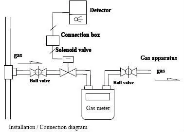 solenoid hydraulic pump motor wiring diagram
What is a 2 2 solenoid valve? This illustrates which wires to connect for either 120, 208 or 240 volt operation.

