The port P0.5 is used to control the pump and the transistor Q6 remains on as the relay also gets activated while the port P0.7 is connected to the LED D7 as an indication of low level in the sump and the LED glows. In this tutorial video, I have explained all the steps to make the homemade PCB for the automatic pump switch.
.png)
[zR2]@c1#J
.q2 [U0v52
5NoA,llgkH1ncy^6$Z48je]d28#-%:tynGy`]&wX(A3N3^p31iQ(6&JR
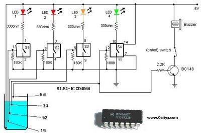
~"Wy;qQ}jkC, Take three wires and name them like LOW, HIGH AND MAIN. After downloading the PCB layout, you can print the word file (.docx) on the A4 page (Please refer to the tutorial video). I have used 555 Timer IC to make this water pump controller. The LED D3, D4 and D5 glow as an indication of the levels (, 1/2 and empty), and then the transistor gets on and the motor will be on. 2 years ago i need to know more about the sensors used here please. Can you sell $1 Automatic Water Level Controller boards, Question 4 years ago. To make the PCB I have used an acrylic sheet. %%EOF
Now, place all the components on the PCB as marked on the layout.

It is also possible to add alarm system to the above circuit which is capable of alerting inmates of a home whenever water levels are high or low or exceeds higher limits. Then Solder all the components. I have shared all the required information for this project. After that, they will review the PCB Gerber file and accordingly confirm the order.

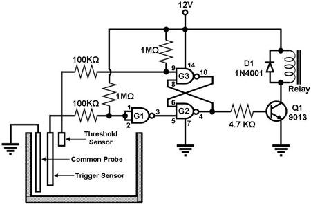
- Structure & Tuning Methods, What is a Full Wave Rectifier : Circuit with Working Theory, What is Transformerless Power Supply & Its Working. And here I have used a 30A relay which can be used up to 1 HP pump. The pump will automatically start for the following conditions, The pump will automatically stop for the following conditions. PCBWay not only produces FR-4 and Aluminum boards, but also advanced PCBs like Rogers, HDI, Flexible and Rigid-Flex boards, at very reasonable prices.For the online instant quote page please visit pcbway.com/orderonline, PCBWay also offers an Assembly service. Wat was the logic needed to support underground sump tank, so that motor runs only when the water is sufficient. why are we taking power of the sensor from the rectifier and not the regulator. At PCBWay, all the boards pass through the most stringent tests other than the basic visual check. with this simple automatic pump controller. The above mentioned circuit consists of four probes arranged in an overhead tank and are interfaced with port 2 of the microcontroller.
The level of the overhead tank is indicated using 5 LEDs, and the pump is switched off when the overhead tank gets completely filled up. on Introduction, Hai, This is prakash. H/~z$) %R You can also make homemade PCB for this project. Why? Water level controller can be used in houses, industries, factories, power plants, chemical plants and other liquid storage systems to save power and money. I have shared all the required information for this project. How to interface ultrasonic sensors with 8051 and how to controll motor ,pls help.

what if I use a 1500mA power supply ? From where we can order some items $1 AUTOMATIC WATER LEVEL CONTROLLER? 2 months ago Now click on the Add Gerber Files to upload the PCB Gerber file. Whenever the water level rises to the maximum, then current flows through the base of the transistor and the collector voltage becomes low and is interfaced with the port p2.4. I have used an acrylic sheet to make the PCB. Also check the underground tank water level. You can also explore different PCB projects from their Open-source community pcbway.com/project/. on Step 3, Question Relay coil voltage: 12V DCRelay Contact Rating: As per the Pump rating. The circuit is very simple, You can easily make this project with some basic electronics components. hj1_e i`;1-hL]8)q)4I9,k6531%`e)$@dGjmGk555b/]c2YU-YVuFmY#N8iV5&!zp44V)YZ}`&W/}T&:nTOu(mnQw#J}YD)u4tts`<9$L So in the following steps, I have explained how to make homemade PCB for Automatic Pump Switch. You can also explore different PCB projects from their Open-source community.

before I go for PCB layout I would like to see back side connection of your PCB as it looks very neatly assembled. I will really appreciate it if you share your valuable feedback.Also if you have any query please write in the comment section. Also, connect the PUMP and AC supply for the PUMP. Do not coil the water level sensor wires together. I have added 2 LED to indicate circuit is online + AC line ON/OFF with a 12v DC 1000mA power supply even you suggest not to add LED for circuit. After that, they will review the Gerber file and accordingly confirm the order. Then click on the Submit Order Now to place the order. There is also an emergency stop switch that you can use to stop the pump manually.

You can also explore different PCB projects from their Open-source community pcbway.com/project/. I tried, but when only main and low that be under water the relay ia flickering.

Before connecting the pump, you can also test the circuit with a test bulb. The programming is done in the microcontroller and sends the data to the microcontroller and LED. To make sensor you dont need anything special. Here, I have explained all the steps to make the homemade PCB for the automatic water pump circuit. Whenever the level distance, which is measured by centimeters falls below a set point limit, the pump starts sensing the ultrasonic module signal coming out from the Transmitter sensor which gets reflected from the level and is received by the ultrasonic Receiver sensor, and then the output is fed to the microcontroller. Can you please tell me where can I get this all electronic components called IC, Resistor, transistor.etc. In this circuit, can 2N2222s be substituted for all 3 transistors and it still function properly (I assume that the bias resistors will have to have lower values)? Now, if the water level in the underground tank comes below UL1 level, the pump will automatically stop although the overhead tank water level is low. Thank you! In this mini electronics project, I have shown how to make an automatic water level controller for the submersible pump and overhead tank with a 555 timer circuit. %PDF-1.5
%
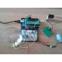
D1 indicates the level of water and the motor switches off automatically whenever the water level goes below the full-level probe, and then the base of the transistor Q2 opens by switching it off; the collector voltage of Q2 is high at P2.4, which means the tank is not full and the same process is applied to the remaining sensing probes , 1/2, 3/4 as they are connected to the base of the transistors q1,q2,q3 and interfaced with the ports p2.5, p2.6, and p2.7 while programming is done within the microcontroller. How to Make Homemade PCB for Automatic Pump Switch, Print the PCB Layout and Stick It on an Acrylic Sheet, Drill the Holes for the Components on the PCB, Place All the Components on PCB As Shown in Layout, Connect the Water Level Sensor Wires and Power Supply With PCB. Here, I have used a 555 DC motor to drill the holes. After that, click on the "Add Gerber Files" to upload the Gerber file. yRwmKU,VH5=p[7-i&I,G#X_Qa>BJhNK8,0RP>ix *E You can also use a hand drill for drilling. You have to select the Relay as per the Pump voltage and current rating. This Automatic submersible motor pump Controller circuit With Three Stage Level Indicator Provides the visual And Attractive LED Indication. Something to ponder. Question This level limit can be varied based on the user requirement by arranging ultrasonic sensor in appropriate place. I hope you have liked this electronics project, Thank you for your time. This water pump controller will also check the water level in the underground tank and automatically ON and OFF the pump according to the water level in the overhead tank. For more details please visit the following articles.Why PCBwayPCB CapabilitiesHigh-Quality PCB. I made it on a breadboard and running for last 3/4 days without any problems. If not, can a 2N2222 be substituted for just the relay driver? Now, connect the water level sensor wires for the overhead and underground tank with the PCB. xV]o6}7G )]~PuH,w(>dYVhLHWM y9~U}.

S9C00
VN dzK#sErqOTB
oA!ru"%GN[\%2XhkZjb'#\W|c8&{,8 p'5fon)qYa0Zx?$B2&K"axd$*,.*GVy[%PB?H0! Step 2: Drill the holes for the components on the PCB. I hope you have liked this electronics project. Step 3: Place & Connect all the components as shown on the PCB layout. Please check the PCB size while printing, it should be the same as mentioned. Question


0
I am using a 12v relay.it can handle 7 Amp AC @240v. They use different testing and inspecting equipment, such as Flying Probe Tester, X-Ray Inspection Machine, Automated Optical Inspection (AOI) Machine, etc to make sure the quality of the final product is always good. The Automatic Water level controller circuit is ready.

When autocomplete results are available use up and down arrows to review and enter to select. At PCBWay, all the boards pass through the most stringent tests other than the basic visual check. Then click on the "Submit Order Now" to place the order for PCB. Here, I have used a DC motor to drill the holes. The Ultrasonic sensor attached to a liquid tank continuously monitors the set level limit and whenever this limit exceeds, the sensor gives input to the microcontroller.
I will really appreciate it if you share your valuable feedback. hb```h B,@q e,`y
rL7H)~cfH6Qa`x. Or you need to make sure everyone knows the way you show the current circuit is not intended for deep well pumps. Here you can control up to 1 HP pump with this controller. Please download the PCB layout, then print it on the A4 page. Here I have used the extra leads of the components to connect those components on PCB. You can order any custom design PCB from PCBWay at a very affordable price. The COM wire should be always under the water level both in the overhead and underground tank. Steps for making the automatic water level controller circuit on PCB: Step 1: Print the PCB Layout and stick it onAcrylic sheet. In this tutorial video, I have explained all the steps to make the homemade PCB for the automatic pump switch circuit. I have used their services for my different electronics projects, I always received the PCB on time and the quality is very good in this reasonable price range. for the overhead and underground tank with the PCB. As the above discussed level control is of contact type wherein the probes are in contact with liquid or water, so there is a chance of it becoming corrosive easily.

Please follow the link: for your exact requirement. `i2vd"X4
Xe
j) ,(`m+*75-0]656fVk5+%LZ_eb`[KlaC98&6QZza*^(V*-Y1 Download and print the PCB Layout. You can also use a hand drill. [Scv{}tcZe7ek 4MsF$g9b_.3GTu{>{(hobnVd6uF@*) In this mini electronics project, I have shown how to make an, for the submersible pump and overhead tank with a, This automatic water pump controller also, I have used a 30A relay to easily control up to. You can alsosubscribeto ournewsletterto receive more such useful electronics projects through email.

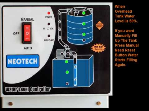
I assume that the BC547 transistor was chosen because of it's gain of 800, but it will not drive more than 100ma. To make a cheap but efficient water level controller under $1 budget to control AC water pump. Download the PCB layout from the following link: https://drive.google.com/file/d/1QGHeY_H826kfZIG8k Now, drill the holes for components on the PCB as per the layout. This automatic water pump controller also checks the water level of the underground tank, before starting the pump. Based on the program, the microcontroller sends control signals to the transistor, which is responsible for switching the relay so that the pump or motor gets turned on or off. Also if you have any query please write in the comment section. At PCBWay, all the boards pass through the most stringent tests other than the basic visual check. The ports P0.0, P0.1, P0.2, P0.3 and P0.4 are interfaced with the LEDs for the purpose of indicating the levels and are connected to the resistors. I have used a 30A relay to easily control up to 1 HP pump with this simple automatic pump controller. In the above picture, the container on the left side is the overhead tank and the container on the right is the underground tank. Now connect the Overhead and Underground tank level wires, 12V DC input, Power supply for the pump, and the water pump as shown in the above picture. wire should be always under the water level both in the overhead and underground tank. hbbd```b``^"Xd?d$S/L9 q*_ We hope that you have got a better understanding with the given circuits and its brief explanation. I hope you have liked this electronics project. endstream
endobj
2017 0 obj
<>stream
Nice and simple!
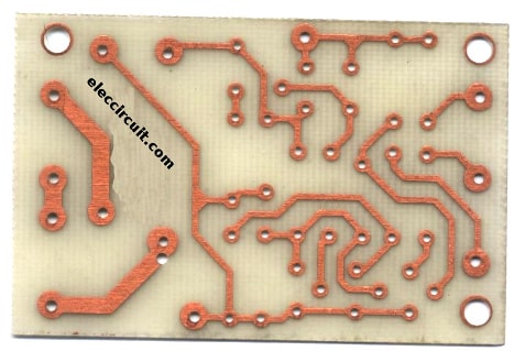
In such contactless liquid level controllers, the mains available power supply is rectified, filtered and regulated to a circuit operating range and is given to the microcontroller and other circuit components. Automatic water level controller/pump controller, Automatic Water Level Controller With Indicator Project 4, Automatic Water Level Controller With Indicator Project 2, This is the PCB layout of automatic water level controller, Automatic Water Pump Controller Circuit for submersible motor using 555, Automatic Water Pump Controller Circuit With Indicator. This type of level-control system is useful where the liquids are of chemical in nature and it is not practical and possible to use contact-type level sensors. Would like to thank you for this useful simple project. And here I have used a 30A relay which can be used up to 1 HP pump. A positive voltage supply is placed at the bottom of the overhead tank, and a full-level probe is placed in the tank and the other end is connected to the base of the transistor Q4 through a resistor R16. on Step 2. Answer Finally place HIGH on the top of the water tank, [ ~~~~~~~~~~~~] -------------------------------------- HIGH, [~~~~~~~~~~~~ ]--------------------------------------- LOW, [______________]--------------------------------------- MAIN, Connect all wires to the main circuit board with help of circuit diagram. endstream
endobj
2014 0 obj
<>/Metadata 164 0 R/Pages 2011 0 R/StructTreeRoot 190 0 R/Type/Catalog>>
endobj
2015 0 obj
<>/MediaBox[0 0 595.44 841.68]/Parent 2011 0 R/Resources<>/ProcSet[/PDF/Text/ImageB/ImageC/ImageI]>>/Rotate 0/StructParents 0/Tabs/S/Type/Page>>
endobj
2016 0 obj
<>stream
kcJ(9$KQQCt7oeGU_08 ~s`L
7,lZ*qQkV]BD
*DLbpCeM0: M Thanks in advance! I would normally substitute a 2N2222 in this instance because it will supply up to 800ma, but it only has a gain of 100. Its a nice project and I am just starting with mine. ~0N4\LH1n7\ja_vBE In this 555 project, I have explained how to make an automatic water level controller for submersible pump using the 555 timer IC. 4 years ago, definitely yes,but you need to tweak the circuit little bit, Question Reply on Step 5. Now the Automatic Water Level Controller PCB is ready. !Rv]rDr;p_4H'9XzeXAQ%n]YmO/oL[c=1hPy=?ai>RC.?RS\dJ;qOr9hz8d3~&[a3zWZ0$l8>5$0QE'}I~RS1#(ACN,IEel2NJwa(b
F,IJ"%8JX>XO ~dh
Reminded my hobbyist days years back! It's to pump out the water from my air conditioner external tank On went is full and go off at the minimum level to not Burns the water pump.
Thank you & Happy Learning, Circuit of the Automatic Water Pump Controller. The probes are arranged in such a way that they sense th, 1/2, th and even full levels as they are placed with equal spacing one above the other with the bottom positive probe. While printing please check the PCB dimension mentioned in the layout. But you can also download the PCB Gerber file for this project, and order the custom design PCB from PCBWay.com. A water-level-controller circuit monitors the level of the overhead tank and spontaneously switches on the water pump whenever the level goes below a specific limit. Please check the website https://www.elprocus.com for complete details in the kit content section and go through the FAQ for details.
To overcome this problem, a water-level indicator with an alarm system is the best option as it controls the water level to an extent that will allow reduction in wastage of water. 3 years ago.